aaptekgsm
A K M P T A
|
Attention : amct team is a subsiediary of A.K.M.P.T.A
|
|
| | Sticky: Collection Mobile Tips & Tricks |  |
|
+8kerryzeng kladeed master_mudieee nighthawk BONUO CELL ™ AMCT KNR AAPTEK FULLFLASHGSM 12 posters | |
| Author | Message |
|---|
FULLFLASHGSM
THE GREAT ADMIN


Age : 42
Job/hobbies : www.apptekgsm.com
|  Subject: Sticky: Collection Mobile Tips & Tricks Subject: Sticky: Collection Mobile Tips & Tricks  Fri Sep 24, 2010 11:36 am Fri Sep 24, 2010 11:36 am | |
| How to repair dead phone
Problems or trouble typically found on mobile phones can be categorized into
Three damage categories, namely:
1. Software Problem category
2. Hardware Problem category
3. Problem Category his SW and HW
Phone problems and solutions
1. Total dead cell phone
Mobile phones exist three kinds of die total, die total because of
· Die alone,
· Total death due to falls, and
· Death total for the taxable water.
a. Total death because death itself.
Handling:
The first can be done early steps following
- Remove the battery and plug in again, or try using another battery and try turn it
- Check the battery connector and try the press to see the level of flexible or not,
replace damaged when new.
- Connect the charging of the phone, when the indicator on the phone in and still will not turn on, then obviously you can not live on mobile phones because of interference from IC PA (Power Amplifier). After IC PA revoked your mobile phone can turn it on again. And so no signal will be installed a new PA IC.
- When the tide does not exist and charging indicator on the phone still does not want to live on should be conducted further tests using power supply. But there may also have an ugly tin on the PCB, remove the IC PA solution, then clean the tin on the PCB where IC PA stick, replace the old IC PA, HP switch, it must be a flame.
Examination with power supply:
Necessary power supply on a scale of 1 ampere ampere (A) or 1000 mA.
With the aim that the examination can be more easily and clearly.
The steps are as follows:
- Connect the cable from the power supply to the mobile phone battery connector of at least three wires, with a negative sequence, BSI and positive. (Black, green and red)
- Navigate volt power supply at 3.6 V (or in accordance with tolerance Hp-0.5 V)
- Mobile phones in the state of OFF, and press the button on
- If the current (amperage) in a digital ampere dipower supply pointer when the button is pressed on, it just means there's still a problem on its hardware (HW), it is necessary to check the components on / off until the battery.
- When the ampere when the button is pressed on, up about? 50 mA, then the problem that occurs is a matter of software (SW), then you need to do is re-programmed HP (flash) or program is upgraded to higher versions.
b. Total death from falls.
Handling:
- HP may not be tested by using the power supply, but HP should be dismantled first, heated, and repositioned back to the location / position of the components has changed as a result of HP fell.
- After that, the new HP using the power supply should be tested to determine damage to the Hardware (HW) / Software (SW).
- Most likely a damaged components as a result of the fall is the HP PA IC / IC Power.
c. Total death due to hit the water.
Handling:
- For taxable HP water is also the first time should not be tested by using the power supply, because the risk of short circuit occurs between the components in water, but must first HP divakum, heated, or by first diblower given IPA cleaning liquid, can also use the grain silica to absorb the water that existed at HP.
- After HP confirmed it was dry, then we should use the power supply to determine the damage occurred on the Hardware (HW) or Software (SW).
- At HP's exposed to water, usually there is damage to HPnya accessories.
2. Total die because of IC phone UI.
In HP's case like this then requires test equipment that is power supply.
The steps are as follows:
- Connect the power supply on the phone, give the voltage (volts) equal to 3.6 V (or in accordance with tolerance Hp-0.5 V)
- At the time the phone is in off state, refer to the power supply needles amperes will increase by 100mA.
- The phone will start, LED lights, VIBRA vibrate.
Handling:
- Remove the IC UI, then turn on the phone.
- Then there is the display on the LCD mobile phone "Insert SIM Card".
- Put new IC UI.
- Turn on the phone, the phone will work fine.
3. Total dead cell phone because the CPU IC.
To determine whether the cell phone because the IC die total CPU is as follows:
- Give the voltage (volts) on the phone by using the power supply of 3.6 V (or in accordance with tolerance Hp-0.5 V).
- At the time the phone is not turned on, the needle ampere silent, but if the phone is switched on then the needle will rise 100mA amperes.
Handling:
- If the IC CPU is still in good condition, then we only need to heat the IC CPU by using a blower, but if the CPU IC is damaged, then we need to replace with a new CPU IC. Before we replace our CPU IC must first have the anti-hot glue and liquid glue crusher anti-heat, because the CPU IC is protected by anti-heat glue, after we destroy the anti-hot glue, then we can heat (blower) CPU IC for a new replacement. Similarly, after we replace it with a new CPU IC then we need to give more anti hot glue to protect the new CPU IC we replace it.
4. Total dead cell phone when we call.
For testing we use the power supply by way of:
- Connect the phone with power supply, give the voltage (volts) equal to 3.6 V (or in accordance with tolerance Hp-0.5 V) on the phone.
- Needles amperes will not move when the phone is still in a state of death.
- We turn on the phone and then used to make calls, then the needle will show the number of amperes above 400mA.
Handling:
- Replace with a new IC PA, after re-testing was done as above, if the needle test results show the figures below 400mA amperes, the phone is in good condition. | |
| | | | FULLFLASHGSM
THE GREAT ADMIN
Age : 42
Job/hobbies : www.apptekgsm.com
| | Subject: Re: Sticky: Collection Mobile Tips & Tricks Fri Sep 24, 2010 11:37 am | |
| How to Work HandPhone
1.3 Introduction
Before you go any further about repairing mobile phones, of course, you must first understand the working principle of mobile phones in order to simplify the process of analysis of damage to the phone.
In this chapter will be discussed in broad outline and in general, because the development of mobile technology today is always changing.
Center 2.3 command processing input / output.
3.2.1 Command input.
Each time you make an order to the phone, for example typing an sms, play games, changing phone settings, voice recording, photos, and others. All of the above command is a command from the mobile phone users, which can pass the command-like device: keypad, camera, infra red, Bluetooth. All input commands will be accepted by the CPU, then the CPU will process all the input commands. CPU can process all the input commands based on system operating data contained in the IC flash. IC flash will store the input data when commanded by the CPU, RAM, while the IC will accept data from the CPU for a while.
3.2.1 Command Output.
CPU will provide overall command of the command input, the command from the CPU is very universal in the overall mobile phone navigation system, for example: giving the order to display graphical information on the LCD, giving orders to the UI (vibrator, buzzer, LED), gives orders to the power supply voltage to meretribusikan , and others.
3.3 Power Supply
3.3.1 Power up / down (On / Off)
The process to turn the phone is not the same as ordinary electronic circuits such as radio, etc. TV. At almost the same phone system with a computer, where the process does not turn on or turn off by disconnect power to the power supply. In the actual computer system if given the power, the system has functioned only in the inactive state, when in analogikan to humans in a state of sleep, which the system will be ready whenever given the command to activate all systems. That's because when the phone has the battery then plug in battery voltage will go straight to the IC power supply, while at the same power supply IC will provide voltage to the processor. SW circuit On / Off cell phone you can see in the image of this diawah.
3.3.1 Distribution voltage
Circuits in cell phones there are many subsystems, which each sub-system has a voltage supply needs of different and at each voltage when the system will be given when necessary. Power given by the first mobile phone battery, the voltage from battrey will continue to power supply IC, the IC power supply voltage supplylah all will be provided depending on needs.
3.3.1 Battery Charging
Mobile phone battery charging process is very thorough at all, whereby the charging system will be computerized. Battery voltage will be in diteksi by the IC power supply and CPU, if the battery in a full state of the phone will reject the filling of the transformer charger. This charging system is processed by charging IC.
3.4 Transmission of information data
Basically, a transmission system in communication systems, there are two systems, the reception (receiver) that serves as reception of data or voice information, alphanumeric data and graphics from the base station to the mobile phone. While the transmitting (Tx) functions as a voice or data transmission information, alphanumeric data, graphics and network registration process
3.4.1 The registration process network
3.4.1.1 Initialization
The first time you make phone calls called by the initialization process. This occurs when you first activate your phone. You'll get a connection from the site terdekekat sell, then the cellular network will perform checks your account or membership is still active or not, then your calls will be processed further.
3.4.1.2 Inspection frequency list
Your phone will check the list of frequencies on your SIM. Inspection covers carrie frequency flow quality, then look for Broadcash Control Channel or BCCH. Each BCCH will transmit a unique data markers, membedan between AMPS and GSM. In the AMPS system uses a dedicated radio frequency system in each cell, whereas on all GSM frequencies can carry information, but more important is the channel used to stream data rather than radio frequency
3.4.1.3 Identification of information
Base station or Broadcash Control Center will continue to deliver for the identification of information about the sell the site. The identity of the wireless network is Carreier itself, then the area code location, and frequency yag used, as well as information about the surrounding cells. All information is used to determine whether your phone is active and in need of service. BCCH is not a radio frequency didedicated. BBCH will use the channel that will carry information in the form of bits at all frequencies within a cell.
3.4.1.4 Control Channel Control Inspection Broadcash
Cell phone radio frequencies will conduct examination bradcash control channel, where your phone will send a signal to review whether the signals are still within range. The phone will be like a radio scanning the entire list of BCCH frequencies one by one and check the signal reception. Measurements will be conducted at each level of the channel. Cell site will send a strong signal to your phone. Meanwhile in broadcash control channel is a mobile data stream from the monitor did ase station called frequency control or frequency control channel burs burs (FCCB). Your mobile phone signals will synchronize with the system provider with wireless connection means. Once your phone has been communicating with the base station, then everything is ready for use.
3.4.2. Transmitting information data
3.4.2.1. signal processing of voice data, graphics, alphanumeric.
While mobile phone users are communicating, then the sound wave signal generated by mobile users will travel through the air. Gelobang voice signal will be received by the microphone to be converted into electromagnetic waves. And will proceed to the audio processor to be strengthened and processed.
If mobile phone users to sms, then type the command on the keyboard by mobile phone users will be processed by the CPU (Central Proccesor Unit)
3.4.2.2. changes in the digital signal into an analog signal (D / A converter).
In this section the data signal information is converted into an analog signal form. Because the RF section is still using an analog signal is shaped in part while the main processor in the form of a digital character. This needs to be an adjustment between two different characters that can be interconnected.
Furthermore, the data signal information already in will continue to convert the RF section.
3.4.2.3. Mixing the data signal with the carrier signal.
Information data signal will be sent to the base station, surely there must be a data signal carrying the information. Therefore, the information data signal will be mixed with the carrier by the RF signal processor. Carrier signal on GSM technology has a 900-1900 MHz frequency range, these waves are initially generated by the VCO, where the VCO will generate a wave of 3420-3840 MHz, which would then be in if the RF processor.
After the data signal information mixed with a carrier signal will then proceed to the section is called the modulation penguatan.sistem.
3.4.2.4. Strengthening end
Signal data information that has been mixed with the carrier signal will be received by the base station, while the distance to the mobile phone base stations far enough. Then the signal has to be really strong to be received by the base station. Then the signal must be reinforced by the PA Power Amplyfier. When strengthening the end of the delivery is not functioning properly then the phone will not be able to register network to the operator, this is caused because the base station can not receive the data signal information from mobile phones.
3.4.2.5. Distribution of Transmission lines
Once confirmed then the signal will be continued to the antenna switch for connecting to the antenna. Antenna switches can be in analogikan like airports, where in the data transmission of information in cell phones, there are two pathways, namely receiving and transmitting. So without the antenna switch on the received signal with the signal to be emitted will collide with each other, because there is only on GSM technology, there is one lane with a system called TDMA.
3.4.2.6. Transmitting to the base station
The next signal will be emitted through the antenna to the base station. Antenna will determine the outcome of the broadcast, then the signal is weak or strong depending on the quality antennanya.
3.4.3. Receipt of information data.
3.4.3.1. Receiving data from the base station
Signal emitted by the base station information to be received in advance by phone antennas. And then be forwarded on to the antenna switch for forwarded to the LNA.
3.4.3.2. Distribution of transmission lines
In order for transmitting signals do not collide with the signal reception, it will be first divided transmission signal by the antenna switch.
3.4.3.3. Strengthening early
So that the signal can be received well by the RF signals emitted by base stations will be strengthened first by the LNA (Low Noise Amplyfier). LNA not only functioned as a reinforcement, but can enable the cutting noise (sigh).
3.4.3.4. Separation of the carrier signal with the signal information
Signals generated by the LNA still mixed with a carrier signal, in order to be processed by the DSP (Digital Signal proccersor) then the data signal information must be separated first by the RF processor. This system is called the frequency.
3.4.3.5. changes in the analog signal into digital signal (D / A converter).
In this section the data signal information is converted into digital signal form. Because the RF section is still using an analog signal is shaped in part while the main processor in the form of a digital character. This needs to be an adjustment between two different characters that can be interconnected.
Furthermore, the data signal information already in the convert will be continued to the main processor (CPU). When the data signal is a voice tersubut information will be continued to the audio amplifier.
3.4.3.6. Strengthening the end of the voice signal
When the data signal information is voice data, it will be reinforced by an audio amplifier terlabih first before continuing to the speakers. Audio signal will be converted into electromagnetic waves, then needs to connect to the speakers so that the electromagnetic signals into sound signals which propagate in the air to be heard by people ears. | |
| | | | FULLFLASHGSM
THE GREAT ADMIN
Age : 42
Job/hobbies : www.apptekgsm.com
| | Subject: Re: Sticky: Collection Mobile Tips & Tricks Fri Sep 24, 2010 11:39 am | |
| How to Work HandPhone
1.3 Introduction
Before you go any further about repairing mobile phones, of course, you must first understand the working principle of mobile phones in order to simplify the process of analysis of damage to the phone.
In this chapter will be discussed in broad outline and in general, because the development of mobile technology today is always changing.
Center 2.3 command processing input / output.
3.2.1 Command input.
Each time you make an order to the phone, for example typing an sms, play games, changing phone settings, voice recording, photos, and others. All of the above command is a command from the mobile phone users, which can pass the command-like device: keypad, camera, infra red, Bluetooth. All input commands will be accepted by the CPU, then the CPU will process all the input commands. CPU can process all the input commands based on system operating data contained in the IC flash. IC flash will store the input data when commanded by the CPU, RAM, while the IC will accept data from the CPU for a while.
3.2.1 Command Output.
CPU will provide overall command of the command input, the command from the CPU is very universal in the overall mobile phone navigation system, for example: giving the order to display graphical information on the LCD, giving orders to the UI (vibrator, buzzer, LED), gives orders to the power supply voltage to meretribusikan , and others.
3.3 Power Supply
3.3.1 Power up / down (On / Off)
The process to turn the phone is not the same as ordinary electronic circuits such as radio, etc. TV. At almost the same phone system with a computer, where the process does not turn on or turn off by disconnect power to the power supply. In the actual computer system if given the power, the system has functioned only in the inactive state, when in analogikan to humans in a state of sleep, which the system will be ready whenever given the command to activate all systems. That's because when the phone has the battery then plug in battery voltage will go straight to the IC power supply, while at the same power supply IC will provide voltage to the processor. SW circuit On / Off cell phone you can see in the image of this diawah.
3.3.1 Distribution voltage
Circuits in cell phones there are many subsystems, which each sub-system has a voltage supply needs of different and at each voltage when the system will be given when necessary. Power given by the first mobile phone battery, the voltage from battrey will continue to power supply IC, the IC power supply voltage supplylah all will be provided depending on needs.
3.3.1 Battery Charging
Mobile phone battery charging process is very thorough at all, whereby the charging system will be computerized. Battery voltage will be in diteksi by the IC power supply and CPU, if the battery in a full state of the phone will reject the filling of the transformer charger. This charging system is processed by charging IC.
3.4 Transmission of information data
Basically, a transmission system in communication systems, there are two systems, the reception (receiver) that serves as reception of data or voice information, alphanumeric data and graphics from the base station to the mobile phone. While the transmitting (Tx) functions as a voice or data transmission information, alphanumeric data, graphics and network registration process
3.4.1 The registration process network
3.4.1.1 Initialization
The first time you make phone calls called by the initialization process. This occurs when you first activate your phone. You'll get a connection from the site terdekekat sell, then the cellular network will perform checks your account or membership is still active or not, then your calls will be processed further.
3.4.1.2 Inspection frequency list
Your phone will check the list of frequencies on your SIM. Inspection covers carrie frequency flow quality, then look for Broadcash Control Channel or BCCH. Each BCCH will transmit a unique data markers, membedan between AMPS and GSM. In the AMPS system uses a dedicated radio frequency system in each cell, whereas on all GSM frequencies can carry information, but more important is the channel used to stream data rather than radio frequency
3.4.1.3 Identification of information
Base station or Broadcash Control Center will continue to deliver for the identification of information about the sell the site. The identity of the wireless network is Carreier itself, then the area code location, and frequency yag used, as well as information about the surrounding cells. All information is used to determine whether your phone is active and in need of service. BCCH is not a radio frequency didedicated. BBCH will use the channel that will carry information in the form of bits at all frequencies within a cell.
3.4.1.4 Control Channel Control Inspection Broadcash
Cell phone radio frequencies will conduct examination bradcash control channel, where your phone will send a signal to review whether the signals are still within range. The phone will be like a radio scanning the entire list of BCCH frequencies one by one and check the signal reception. Measurements will be conducted at each level of the channel. Cell site will send a strong signal to your phone. Meanwhile in broadcash control channel is a mobile data stream from the monitor did ase station called frequency control or frequency control channel burs burs (FCCB). Your mobile phone signals will synchronize with the system provider with wireless connection means. Once your phone has been communicating with the base station, then everything is ready for use.
3.4.2. Transmitting information data
3.4.2.1. signal processing of voice data, graphics, alphanumeric.
While mobile phone users are communicating, then the sound wave signal generated by mobile users will travel through the air. Gelobang voice signal will be received by the microphone to be converted into electromagnetic waves. And will proceed to the audio processor to be strengthened and processed.
If mobile phone users to sms, then type the command on the keyboard by mobile phone users will be processed by the CPU (Central Proccesor Unit)
3.4.2.2. changes in the digital signal into an analog signal (D / A converter).
In this section the data signal information is converted into an analog signal form. Because the RF section is still using an analog signal is shaped in part while the main processor in the form of a digital character. This needs to be an adjustment between two different characters that can be interconnected.
Furthermore, the data signal information already in will continue to convert the RF section.
3.4.2.3. Mixing the data signal with the carrier signal.
Information data signal will be sent to the base station, surely there must be a data signal carrying the information. Therefore, the information data signal will be mixed with the carrier by the RF signal processor. Carrier signal on GSM technology has a 900-1900 MHz frequency range, these waves are initially generated by the VCO, where the VCO will generate a wave of 3420-3840 MHz, which would then be in if the RF processor.
After the data signal information mixed with a carrier signal will then proceed to the section is called the modulation penguatan.sistem.
3.4.2.4. Strengthening end
Signal data information that has been mixed with the carrier signal will be received by the base station, while the distance to the mobile phone base stations far enough. Then the signal has to be really strong to be received by the base station. Then the signal must be reinforced by the PA Power Amplyfier. When strengthening the end of the delivery is not functioning properly then the phone will not be able to register network to the operator, this is caused because the base station can not receive the data signal information from mobile phones.
3.4.2.5. Distribution of Transmission lines
Once confirmed then the signal will be continued to the antenna switch for connecting to the antenna. Antenna switches can be in analogikan like airports, where in the data transmission of information in cell phones, there are two pathways, namely receiving and transmitting. So without the antenna switch on the received signal with the signal to be emitted will collide with each other, because there is only on GSM technology, there is one lane with a system called TDMA.
3.4.2.6. Transmitting to the base station
The next signal will be emitted through the antenna to the base station. Antenna will determine the outcome of the broadcast, then the signal is weak or strong depending on the quality antennanya.
3.4.3. Receipt of information data.
3.4.3.1. Receiving data from the base station
Signal emitted by the base station information to be received in advance by phone antennas. And then be forwarded on to the antenna switch for forwarded to the LNA.
3.4.3.2. Distribution of transmission lines
In order for transmitting signals do not collide with the signal reception, it will be first divided transmission signal by the antenna switch.
3.4.3.3. Strengthening early
So that the signal can be received well by the RF signals emitted by base stations will be strengthened first by the LNA (Low Noise Amplyfier). LNA not only functioned as a reinforcement, but can enable the cutting noise (sigh).
3.4.3.4. Separation of the carrier signal with the signal information
Signals generated by the LNA still mixed with a carrier signal, in order to be processed by the DSP (Digital Signal proccersor) then the data signal information must be separated first by the RF processor. This system is called the frequency.
3.4.3.5. changes in the analog signal into digital signal (D / A converter).
In this section the data signal information is converted into digital signal form. Because the RF section is still using an analog signal is shaped in part while the main processor in the form of a digital character. This needs to be an adjustment between two different characters that can be interconnected.
Furthermore, the data signal information already in the convert will be continued to the main processor (CPU). When the data signal is a voice tersubut information will be continued to the audio amplifier.
3.4.3.6. Strengthening the end of the voice signal
When the data signal information is voice data, it will be reinforced by an audio amplifier terlabih first before continuing to the speakers. Audio signal will be converted into electromagnetic waves, then needs to connect to the speakers so that the electromagnetic signals into sound signals which propagate in the air to be heard by people ears.
wawan_berau is offline Add Infraction for wawan_berau Report Post IP
Digg this Post!Add Post to del.icio.usBookmark Post in TechnoratiFurl this Post!
Edit/Delete Message Reply With Quote Multi-Quote This Message Quick reply to this message | |
| | | | FULLFLASHGSM
THE GREAT ADMIN
Age : 42
Job/hobbies : www.apptekgsm.com
| | Subject: Re: Sticky: Collection Mobile Tips & Tricks Fri Sep 24, 2010 11:41 am | |
| Cellphone Basics EXPLANATION OF THE BASIC THEORY OF OPERATION OF A MOBILE PHONE IN A VERY SIMPLE WAY: HAVE YOU EXPERIENCED THE FACT THAT IN A MUSIC LISTENED FROM A VERY LONG DISTANCE, THE SOUNDS OF DRUMS ARE LESS AUDIBLE THAN THE SOUNDS OF OTHER SHARP INSTRUMENTS LIKE GUITAR ? YES THIS IS BECAUSE THE SOUND OF A DRUM IS A LOW FREQUENCY SIGNAL AND LOW FREQUENCIES CANNOT TRAVEL LONG DISTANCES EASILY WHILE THE HIGH FREQUENCIES LIKE THE SOUND OF GUITAR OR OTHER STRING INSTRUMENTS CAN ! SEE HOW THIS IS APPLIED IN THE RADIO, TV AND MOBILE TECHNOLOGY FOR YOURSELF. AFTER ALL THE MOBILE PHONE IS ALSO A RADIO TELEPHONE ! THE BROAD MEANING OF THE WORD "RADIO" IS WIRELESS. THE PRINCIPLE OF A MOBILE PHONE CAN BE COMPARED WITH THAT OF A RADIO OR A TELEVISION SYSTEM. There are two parts in mobile phone 1. is Transmiting & 2. is Receiving TRANSMITTING PART.. THE VOICE SIGNAL WHICH IS BASICALLY IN THE FREQUENCY RANGE OF 15 HERTZ TO ABOUT 20 KILOHERTZ (1KILOHERTZ=1000 HERTZ)AND IS IN THE LOWEST FREQ.BAND IN THE NORMAL FREQUENCY SPECTRUM, WHICH IS REQUIRED TO BE SENT TO THE OTHER MOBILE PHONE IS FIRST CONVERTED FROM ANALOG TO DIGITAL TYPE OF SIGNAL AND IS THEN MIXED WITH A VERY HIGH FREQUENCY SIGNAL IN THE RANGE OF HUNDREDS OF MEGAHERTZ (1 MEGAHERTZ = 1000KILOHERTZ=1000X1000 HERTZ=1000000 HERTZ) IN THE MOBILE PHONE , THIS IS CALLED MODULATION, WHICH MEANS CHANGING THE AUDIO SIGNAL BY ADDING ANOTHER VERY HIGH FREQUENCY TO IT , THE HIGH FREQUENCY BEING USED AS CARRIER FREQUENCY TO CARRY THE VOICE OR THE AUDIO SIGNAL. THIS IS DONE TO MAKE IT POSSIBLE TO BE SENT THRO' AIR TO THE NEAREST TOWER OF THE SERVICE OPERATOR. THE BASIC PRINCIPLE BEING THAT THE HIGH FREQUENCIES CAN TRAVEL LONGER DISTANCES EASILY. RECEIVING PART IN THE RECEIVING PART, THE REVERSE (DE-MODULATION) IS REQUIRED TO BE DONE. THE RECEIVED SIGNAL FROM THE SERVICE OPERATOR'S TOWER IS REQUIRED TO BE DEMODULATED TO REMOVE THE HIGH FREQUENCY SIGNAL OR THE CARRIER FREQUENCY SIGNAL FROM THE RECEIVED SIGNAL, SO THAT ONLY DIGITAL AUDIO SIGNAL IS LEFT OUT. IN MOBILE PHONES, THIS DIGITAL AUDIO SIGNAL IS THEN CONVERTED TO ANALOG SIGNAL AND AFTER SOME AMPLIFICATION ETC. IS SENT TO THE SPEAKER TO BE HEARD BY THE USER. BOTH THIS TRANSMITTING (TX) AND RECEIVING (RX) FUNCTIONS ARE REQUIRED TO BE CARRIED OUT IN THE MOBILE PHONE ITSELF AND IS DONE BY WHAT CAN BE CALLED THE RF SECTION OF THE MOBILE. What is Frequency ? What is frequency? and what are mobile frequencies? Mobile phone uses radio waves to communicate with other mobile phones and when you are face to face with radio waves you have to learn about frequencies. The word frequency is derived from the word frequently which is used with the meaning of circulation of any task repeated with same time period. so if any task is repeated with a same time period you can call its ratio as frequency. In radio waves a the speed of waves going up and down is called frequency and it is measured in Hz(Hertz). if a wave finishes its ten cycles in a second its frequency will be 10 Hz. look at the chart below to learn more about the frequencies. 1 cycle/second = 1Hz 1000 Hz =1Kilo Hertz (1Khz) 1000Khz =1 Mega Hertz (1Mhz) 1000Mhz =1 Giga Hertz (1Ghz) 1000Ghz = 1 Tera hertz (1Thz)  Cell Technology Geographic areas are divided into a number of slightly overlapping circular "cells." Each cell contains a base station, which is identifiable by its transmitting and receiving antenna located on a tower at the top of a hill or building. The base stations connect to the landline telephone system of the country. The multiple cells combined with low power transmitters allow the same frequencies to be reused with different conversations in different cells within the same city or locale. The primary digital cellphone technologies are TDMA, CDMA and GSM. see cellsite.  Lets see the first GSM mobile phone how it looks like! First Cellphone in U.S. Introduced in 1983, this Motorola DynaTAC cost $3,995 and weighed two pounds. (Image courtesy of Motorola, Inc.)  Mobile phone features Main article: Mobile phone features Mobile phones often have features beyond sending text messages and making voice callsââ‚ƚ¬Ã¢â‚¬ÂÂÂ�including Internet browsing, music (MP3) playback, personal organizers, e-mail, built-in cameras and camcorders, ringtones, games, radio, Push-to-Talk (PTT), infrared and Bluetooth connectivity, call registers, ability to watch streaming video or download video for later viewing, and serving as a wireless modem for a PC. Technology Mobile phone tower Mobile phones and the network they operate under vary significantly from provider to provider, and even from nation to nation. However, all of them communicate through electromagnetic radio waves with a cell site base station, the antennas of which are usually mounted on a tower, pole, or building. The phones have a low-power transceiver that transmits voice and data to the nearest cell sites, usually .5 to 8 miles (0.8 to 13 kilometres) away. When the cellular phone or data device is turned on, it registers with the mobile telephone exchange, or switch, with its unique identifiers, and will then be alerted by the mobile switch when there is an incoming telephone call. The handset constantly listens for the strongest signal being received from the surrounding base stations. As the user moves around the network, the mobile device will "handoff" to various cell sites during calls, or while waiting (idle) between calls it will reselect cell sites. Cell sites have relatively low-power (often only one or two watts) radio transmitters which broadcast their presence and relay communications between the mobile handsets and the switch. The switch in turn connects the call to another subscriber of the same wireless service provider or to the public telephone network, which includes the networks of other wireless carriers. The dialogue between the handset and the cell site is a stream of digital data that includes digitized audio (except for the first generation analog networks). The technology that achieves this depends on the system which the mobile phone operator has adopted. Some technologies include AMPS for analog, and TDMA, CDMA, GSM, GPRS, EV-DO, and UMTS for digital communications. Each network operator has a unique radio frequency band. | |
| | | | FULLFLASHGSM
THE GREAT ADMIN
Age : 42
Job/hobbies : www.apptekgsm.com
| | Subject: Re: Sticky: Collection Mobile Tips & Tricks Fri Sep 24, 2010 11:42 am | |
| Basic Terms used in nokia flashing
Flash files to download and install
example:
RM-38_v 11.00 (mcusw 4.14) Emea Apac China LTA
this called major version, must be installed first before you can install minor version.
contains MCU, PPM, and CNT.
RM-38_v 11.01 (mcusw 4.14) Emea Apac China LTA
called minor version, can be installed after major version installed, usually contains only PPM and CNT (no MCU, but for some other type, maybe contains MCU newer version also)
another example:
RM-36_v 8.00 (mcusw 5.050407) Euro
for EURO countries
RM-36_v 9.00 (mcusw 5.050440) Apac
for Asia Pacific countries
================================================== ==============
DCT4 tab
1. Checking phone, cables, software version etc.
Flash settings tab
MCU : Micro Control Unit
PPM : Post Programming Memory, contains language
CNT : Content Pack, contains tones, games, etc
ADSP : Advance Digital Signal Processor, flash file for DSP chips
APE : Application Processor Engine
Use INI :
When you thick this, software will detect phone connected type, and “Use INI” files setting when exist in “Product Directory” for choosing flash files.
INI : (*.ini)
This file contains flash files setting for each “Product Code”, including MCU, PPM, CNT, PP (Product Profile), etc.
(Even in 3250, different product code may have different MCU to be flashed).
These files are extracted from firmware/data package that we have installed.
Use this option in order to avoid choosing wrong flash files, example :
- If you don’t know for sure which MCU, PPM, or CNT.
- Choose right PPM for language that you want
- How to choose right CNT that suitable with your PPM
After a Product Code has been chosen automatically, you can change it manually with other Product Code that you want to flash.
Run INI :
After flashing completed, software will upload also Product Profile according INI that has been chosen and flashed.
Product Profile :
This file contains customization for each Product Code, example : GPRS settings, WAP bookmarks, etc..
For Communicator Phone, this file also contains keyboard layout.
Load NFP:
NFP: Nokia File Protected
Data package (MCU, PPM, and CNT) for nokia CDMA phone was compressed as a file :
*.NFP, and it is protected by password.
Thick this option, choose *.NFP, software will extracted it automatically as MCU, PPM, and CNT.
Easy Cable :
It’s a special cable, suitable with pop-up connector for few type phone, ex : 1600, which can be use for flashing. Thick this if you use this kind of cable.
RPL 208 :
PM field number 208 was copied from DATA1/ IMEI flash data.
Software will back up this area as RPL(DATA1 only), that useful for recover flash IMEI if something happen after flash (IMEI ????), or you changed flash IC, you no need to change UEM also if you have back up for this phone. Some type don’t have this field, like 1100, 2300, etc. Make sure your phone can enter Local Mode for this option.
FTD ON:
FTD : Field Test Display / Net Monitor : special menu for DCT4 and DCT4 TIKU that can be activated with flashing, it contains many feature for testing phone and network.
Product Code :
Every Nokia phone has 7digit number that written in the back sticker.
This Product Code will differ phone that sold to one country and another, also phone that sold with customization for an operator, will have different Product Code also.
This number also saved somewhere in PM area.
Thick “Change Product Code” will change Product Code number in PM area after flashing completed.
Factory Set :
Reset all settings to factory default after flash completed.
Manual Flash:
this option will disable software detect the phone model and open his folder when you click on “MCU”, “PPM”, etc, or thick on “Use INI”
Warranty :
When you press *#warranty# or *#92702689#, phone will display some hidden information like Serial Number, Made, etc, including “Life Timer”.
This option after flash will reset “Life Timer” back to zero after flashed.
Unlock:
Initialize sim lock after flash
Erase :
normally, software will erase first some area according Flash Files needed before writing them. If you thick this option, without erase first, software will write the Flash Files that have been chosen. Use this option only if you already have fully erased the phone manually.
Skip AFP :
AFP : After Flash Processing
After flashing completed, software will try to put the phone into Local Mode and read some info about it. This option will disable that process.
Use this only if you know why this process should be skip, example you flash an Erase
File that make the phone dead/ fully erase.
Not all Erase File erase whole part of flash IC, some Erase File only erase some part of flash IC and phone still alives.
Skip MCU ID :
MCU ID is UPP (Universal Phone Processor) recognition, inside flash file, there’s recognition for MCU ID that supported (by that flash file).
Use this option only if you sure that you flash the phone with right flash file, but software give warning that MCU ID is not supported by flash file that have you choose.
Note : usually warning about MCU ID is not supported but right Flash Files has been chosen is caused by bad cable connection. Try restart software, reconnect F-Bus cable from phone, and try again.
For dead phone suspected / possibility hardware problem, if MCU flashing has been completed, continue flashing with PPM only usually will solve.
BT :
Bluetooth IC have own firmware including in MCU file.
You may skip this if you flash the phone with same version, this will save flashing time a little.
But you have to skip this if BT IC is damage, it’s indicated with when you flash a phone and software error in the middle with warning : “Error loading additional loader..”
INF : INFO
Make sure your phone can enter Local or Test mode for this operation.
At the end of this operation, software will detect phone’s Product Code and load Flash Files according it.
If no suitable product code found, you must thick “Manual Flash” and then “Use INI”,software will ask you to “Select Phone Model”.
You can sort it by “Type” or by “Name”, or you can type phone code like RH-12, and all “INI” settings for this phone will be loaded, and can be chosen.
Note : if you don’t find your phone type or name in the list, but you have Data Package installed for this phone, open “nok4models.ini” with Notepad and add it like this
[RM-307]
CHK : Check
Will check phone hardware condition like
- Relation between UEM (Universal Energy Management - power IC) and UPP (Universal Phone Processor)
- MCU ID / UPP
- Flash IC
- RAM IC
- First 16 bytes
- FAID Calculation
Remember, bad F-Bus cable also make this operation failed !!!
Service:
This button related with “Service Operations” tab
Erase Flash:
Software will try to back up RPL 208 if your phone can enter Local Mode or IMEI Flash Data not corrupted, or RP 208 exist, and then check phone hardware like MCU ID, etc and display Erase Flash Manager.
Flash Chip List:
Below this tab you can choose which IC that you want to erase, and you can modify Erase Address.
Start Address always 0×000000 and End Address always 0xxFFFFF, depends on Flash IC size.
FULL Erase :
Full Erase will erase all Flash IC, including PM (Permanent Memory), & will make SIM Lock Data corrupted.
Make sure that you have back up PM to be uploaded after flash and unlock after this operation.
Click Start Erase to execute this operation.
PM : Permanent Memory, an area in flash IC that wasn’t reached by flash files, means normal flashing shouldn’t change it’s value.
It contains data of RF, EM, Product Code, Security Code, and so many more.
For some type it also contains backup IMEI Flash Data, even phone book and gallery content. PM file can be opened with Notepad or Wordpad.
PM area indicates with :
Field Number 0 - xxx (some type has field numbers <200, some has <255, but newer phone type may have 300>).
Each “Field Number” may has sub “Record Number”
Field Number indicates with : [x]
And Record Number indicates with : x=
If you fully erase a phone, you can upload PM that you have read from another phone which same type, but make sure you have deleted field 5, 120, and 208 from it, ’caused it contains IMEI data.
Repair BT / Repair Bluetooth :
Same with erase PM field 4 index 17 (4:17) that contains BT address.
Some type of Nokia phone save BT address in this field, if this area corrupt or filled with another BT address (maybe caused by upload PM from another phone), & BT can not be switch on, try use this option.
Read Fls ….
Prod Dir :
Change default Flash File detection from C:\Program Files\Nokia\Phoenix to another.
FLASH : start flashing
(Un)Lock:
this button related with “Unlock settings” tab
Init simlock : Initialize SIM Lock, remove Operator SIM Lock restriction
Write SIM file : write file *.SIM that contains SIM Lock settings.
Code Calculator : calculate codes from IMEI number, network code, and ASIC code, for initialize SIM Lock, enter it with type the codes manually with keypad
Read Codes : read phone for IMEI and calculate code for initialize SIM Lock
Auto Lock: after this operation, phone will recognize network code from first SIM Card that inserted to phone, and lock to this network.
Autolock IMSI :
IMSI : International Mobile Subscriber Identity, after this operation, phone will recognize first SIM Card that inserted and lock phone to this SIM.
Lock to Network: enter the network code manually and phone will be lock to this network
Load JAVA :
Upload JAVA application to the phone
MMC Rst:
with special cable adapter, this will reset locked Memory Card
Make INI:
If you have chosen your flash file manually or USE INI, this operation will create your own “INI file” for that type. After this, software will automatically load that flash files after INF pressed.
IMEI tool:
There are 2 IMEI in DCT4 phone:
First is in UEM, also called DATA2, OTP (one time programmable).
Second in flash IC, also called DATA1, not OTP.
If DATA1 get corrupted or not synchronize with DATA2, Watchdog timer will be enabled, phone will be restart after +/- 30 seconds. You will see software says IMEI ?????????
Make ASK: make “ask” file to be calculated become RPL.
This operation is used after you change UEM and want same IMEI number with your phone previously (IMEI at back cover sticker), or you have change flash IC but don’t have back up for this.
Thick “UEM Changed” in order to get DATA2 calculation also,
otherwise ASK will be calculated only for Flash IC / DATA1.
Write RPL (reply) :
Because there are 2 IMEI in DCT4 phone, RPL may contains DATA1 only or DATA1 & DATA2. You can open it with Notepad/Wordpad.
RPL from back up RPL 208 contains only DATA1, will be uploaded to flash IC.
RPL from ASK calculation can be contains 2 data (remember about thick “UEM changed” when make ASK), one will be uploaded to flash IC : DATA1, and the other one will be uploaded to UEM: DATA2.
If you changed UEM, DATA2 will be wrote and become OTP IMEI. No problem if RPL contains 2 data but you did not change UEM, as long as DATA1 and DATA2 are synchronized, phone will be normal.
ASIC : Application Specific Integrated Circuit
class of DCT4 phone:
ASIC 2
ASIC 5 - WD2
ASIC 6 - TIKU BT
ASIC 7
ASIC 11
If you changed UEM and do not want to calculated RPL, you can use “free supplied rpl” that come with software installation, but you have to write RPL with same ASIC to your phone.
IMEI Patch:
this will “patched” IMEI Plain, IMEI that showed by pressing *#06#, with desired IMEI that you want. Patch options only work for DCT4 ASIC2.
And this only work for normal phone, means patch WILL NOT SOLVE problem IMEI ????????? that ’caused by DATA1 corrupted.
If you try this with phone that have problem IMEI ?????????, Watchdog timer will be enabled, and your phone will restart after +/- 30 seconds.
IMEI Save: back up PM 208 as RPL
Unlock : Initialize SIM Lock , needed after write RPL
Read UEM : Read UEM IMEI
If you have phone with IMEI ?????????, check also whether UEM IMEI still good.
If yes, read ASK, calculate ASK to RPL, and write RPL.
But if UEM IMEI also damage, you have to Change UEM.
Service Operations tab: (use Service button to execute)
Make sure you phone able to enter local and test mode for this service.
If not, check the cable or maybe phone have hardware problem.
Read, Write, and erase PM : look above about PM.
Self Test : test some phone conditions via software.
Always use this feature if your phone has “Contact Service” problem that can not be solve with erasing and flashing.
Disp Test : LCD test.
Upload TUN : RF value for CDMA phone was saved with file named *.tun.
Factory Setting: reset the phone to factory settings
Prod. Manager :
Read or change/write some value that saved in PM area:
- Product code
- HW version : Hardware Version : please be careful edit this for RM-72 - 6230i, ’cause PPM and CNT flash file was different between old and new HW version.
- Order Number
- Production SN
- Manufacture Month : in phone showed by typing *#warranty#
File System Format:
Format User Area of the phone, user data will be lost.
Remember that WD2 have different File System with DCT4 TIKU as example.
WD2 = Symbian EPOC, Drive for User Area : C
DCT4 TIKU : FILE2 , use Format Type : Low Level Format, and type : NAND
So, if software can not detect File System correctly, try making Full Factory before execute this again.
User Code Edit:
Read Security Code which saved at PM filed number 35.
Upload and Read PP:
please look above “Product Profile”
ADC Read :
Analog to Digital Converter : some Self Test about phone battery, charger, etc
Fun Explorer :
About exploring JAVA application in DCT4 phone.
Warranty Reset :
look above about Warranty.
Phone Mode:
(?) read phone status
change phone mode to
Local Mode
Test Mode
Normal Mode
Communication Mode:
F-Bus cable : flasher cable
USB: DKU-2/CA-53, when you connect DCT4 TIKU with this cable, you will be able to make some operation like : make Full factory, Init SIM Lock, etc, but not for flashing.
——————————————————————–
Flashing DCT4 APE phone : 9300, 9500, and 7710:
connect both F-Bus cable and USB cable (DKU-2 CA-53) to phone.
when you make CHK for this phone, System Tray in Windows will give warning about “USB DEVICE NOT RECOGNIZE”, this is normal, and this must be happen.
If you don’t get this warning, you need to check again USB connection to phone, otherwise phone may have hardware problem.
During flashing process windows will install drivers needed for flashing this phone.
================================================== =================
BB5 tab
BB5 phone :
BB : Base Band
Single chip : have only CMT processor. example : 6270, 62880, etc
Dual chip : have two processor, CMT (cellular Mobile telephone) and APE (Application Processor Engine) example : 6630, 6680, N70, etc.
Communication Mode:
F-BUS cable : use only 7 pins cable for flashing with JAF box.
Make sure your phone can enter Local or Test Mode !!!
If not, maybe you need to check your cable, and then modified it, if not suitable with box specification.
1. NEVER EVER try putting 9v battery in F-BUS cable though your cable has this connector !!!
2. Resistance between BSI-GND must be 68k ohms, if less than it, maybe you will find “error sync the phone when make “CHK”
3. Resistance in BSI serial must be 5,1k(5k1) or 7,5k(7k5) ohms. Otherwise your phone can not enter Local / Test Mode.
4. Make sure VPP line from RJ45 connected to RX2 in phone.
Never use cable that connected VPP line in RJ45 with VPP in phone, you will get error something like “Error APE get id”
I don’t give explanation about P-KEY and UFS Box, because newer BB5 phone with RAPIDO processor doesn’t supported by UFS Box.
USB : all (alive) BB5 phone supported by USB flashing, you may use DKU-2 or CA-53, but some types needs DKE-2/mini USB for this operation. make sure your battery fully charged, or charge it with an original charger before start flashing.
When you flash phone and software give error warning “error getting flash id”,
put sim card inside, do not select offline mode, and flash the phone.
Note : make sure you disable all connection in PC Suite (if you installed Nokia PC Suite software in your PC) when using this service.
Dead USB :
Few types of BB5 with single chips supported by “Dead USB flashing”.
Choose flash file manually, connect USB cable to phone, and when software give command to “press the power now”, press switch on/off briefly. In windows systems try, will show “Nokia USB ROM”, and windows will install the driver automatically.
For some types, successfully dead USB flashing will revive the phone, but gallery content will be empty, so you need to flash again with USB as normally.
Downgrade :
This option based on Dejan’s trick to be able to flash a working/normal BB5 phone with lower version.
Maybe not all BB5 supported by this option. So, if you try downgrade and the phone become dead, flash again with latest/highest firmware version.
CRT 308:
PM field number 308 contains SIM Lock data, make sure your phone can enter Local Mode before flash, in order to make successful back up.
If something wrong after flashing process and SIM Lock Data become corrupted, use Write PM and choose this back up to be written to the phone. Your sim lock state will back like before flashing.
CRT BKP: Certificate Back Up, saved as *.RPL.
Skip APE: skip APE flashing.
SX4 Authority :
BB5 phones have protection for writing RF(1 ) and Energy(309, 0×135 in hex) settings in EPROM. Not having those settings in phone, is known as ‘Contact Retailer Problem’, or ‘Security Error’ in Self Test. In order to write those settings phone requires an authorization that only SX4 Smart Card can perform.
As those cards are hard to get, software can use server support for this authorization.
To authorize, connect BB5 phone, and power it on.
Press “SX4 AUTH”. If you have SX4 card connected to PC, software will use it to compute the authorization password and send it to phone.
If you don’t have card, software will connect to server to compute authorization password.
If this process have sucessfuly done, Write PM to the phone without field number 308.
================================================== =============
Update Loaders:
FIA = Flash Identification Address are files that needed for flashing, to identify MCU ID and Flash Files which suitable with phones. If you press this, software will check whether new version from support site exist and replace your flash loaders with new one if you download it.
================================================== =============
Phone phone terminals
VBat - Battery Voltage
BSI - Battery size Indicator
GND - Ground, conductive mass | |
| | | | FULLFLASHGSM
THE GREAT ADMIN
Age : 42
Job/hobbies : www.apptekgsm.com
| | Subject: Re: Sticky: Collection Mobile Tips & Tricks Fri Sep 24, 2010 11:43 am | |
| How to Repair Mobile Phone Charging Problems Issues
I prepare to used the Nokia Mobile Phone as a set example of this lesson, for Nokia is the most efficient mobile phone to fix for which they provide all source of service manuals and diagrams aside from other mobile phone products on the planet today.
Basically there are many types of charging problems not just in Nokia Handset but all mobile phones products like Samsung,LG,Sony Ericsson, Motorola,iPhone, Blackberry and etc.
like:
Not Charging - When the charger is being plug-in and it shows the word on the display "Not Charging"
Charger Not Supported some sort of like the charger is not compatible with the handset but the problem actually exist on the charging circuit.
No Response - this is what this problem called when even a good and working charger is being plug-in, The handset shows no response or no reaction when the charger is being plug-in.
Fake Charging - The handset is charging by itself even without any charger plug unto it, or the indicator shows that the handset is charging when the charger plug unto it but the battery haven't not charge any voltage or current at all.
Invalid Charger- The handset responds that the charger is invalid and not compatible with the handset.
Those Charging problem issues mentioned above were just common types of faulty charging circuits within any various mobile phone handsets exist before and nowadays.
Experts and Professional Technician have different techniques when it comes to troubleshoot such problems. But mostly all of them start on the basic method on how to find the faulty component or parts within that certain problem.
Now, typically mostly hardware troubleshooters starts within this following methods below.
1. Checking up the charger if the charger is good, weak or being damaged, or try to use other good and working charger to compare if the charging problem still exist.
The picture below is a typical layout of a common mobile phone charger. It converts the AC (Alternating Current)voltage coming from an outlet then convert it into a DC voltage. It has "+" positive and "-" negative polarity. A common mobile phone charger range from 4.5 to 6 volts DC(Direct Current)
Various mobile phone products charger have different types of pin connectors layout and packaging but the operational circuit took inside it almost all the same.
2. Checking up the battery if it is still working or weak and test its Voltage and currents or replace with a good and working one.
3. Checking up the Charging Pin Connector by visualization and see to it for some breakage or some dust and dirt corrosion. Corrosive element such moisture may also cause the problem and see to it that is clean and free of any corrosive objects.
4. Checking up the Charging Terminal Contact Pads if it is free from any dust and dirt and making sure that it is totally clean.
5. Then Proceed to Component Fault Finding Method if found that the earlier mentioned above was all fine but the problem still exist.
In component fault finding method it is also advice to start from the basic test and check up procedures on every components within a certain circuits area. There are so many free and shared solutions scattered away among so many gsm forum communities. Some of them were pictures of jumpers and modification methods and lack of step by step procedure instructions, it is because those certain solutions were belong to all exactly understand the whole circuitry and not for the beginners. That is why only those masters and experts alike only can catch up what was that all about.
But not always happens like that, there are also many experts that always think the benefit of the new learners which he emphasized some step by step procedure on where to start to troubleshoot or test.
In continuation of this lesson I prepare here the basic Understanding of Mobile Phones Charging Circuit for Beginners. | |
| | | | FULLFLASHGSM
THE GREAT ADMIN
Age : 42
Job/hobbies : www.apptekgsm.com
| | Subject: Re: Sticky: Collection Mobile Tips & Tricks Fri Sep 24, 2010 11:45 am | |
| All Beginner Service
Basic Electronics
________________________________________
However a mobile phone is an electronic circuit that is very smart and sophisticated. But the phone can not function when not given the power or voltage (electricity).
Maybe you already feel the benefits of an electric, if you know them from the power characters? Did you ever see the electricity? Did you ever see the electric current? Of course not! Can we feel the benefits of electricity, but electricity can not we see a form of existence, if you are curious about the existence of electric please you touch with your finger to the outlet in your house, hehehe .. shock is not it? Well, with a little experimentation is of course you already can feel the electricity.
Well I will try to introduce practical about electricity, it's a bit difficult to describe an electrical circuit because electricity can not be seen, whereas when we repaired the phone of course we must know the value of the voltage to the range of phones, whether we can know by simply looking at it? No! Needed a measure to find out, for example: avometer, frequency counters, osciloscope, spectrume analizer, etc..
Power source
________________________________________
Initially of course there is the question of what will be the beginning of electricity? Is this universe since the creation of electricity already exists? Yup! Electricity has been around since God created the universe. Obviously you also can feel the power of nature, when the weather was cloudy due to rain, the electricity was caused by lightning, a very large force, it can burn anything that grabbed.
The scientists eventually observed the presence of electronics on electric and natural scientists are finally able to create artificial electricity. With technological developments ultimately the source of electricity can be generated by:
1. Electricity chemical derived from the chemical process stone car battery or accumulator. Electricity is only unidirectional flow only, and is called direct current, abbreviated DC. DC power has a positive polarity (+) and Negative (-), then their use should not be installed upside down.
2. Electricity generated by electricity generators, which are distributed through a transformer and distributed to consumers (users) of electricity. Electricity generated by the generator flows back and forth, and is called the alternating current, abbreviated as AC. AC power is different from the DC power that have unidirectional polarity, polarity AC power will be subject to change, let's say the AC power at home that has electric 220Volt voltage with frequency 50Hz, then the polarity will change as much as 50 times a second. In use, the flow of AC power plug upside down is no problem though.
With the current development of electronics technology, electrical alternating current (AC) can be used as direct current (DC) by using an instrument called a power supply or adapter, the device will be on the phone accesories such as transformers meet charger used to charge battery phone.
Current and voltage
________________________________________
Electric charge that moves us as the electrical current. The magnitude of the electric current can be defined as the amount of cargo that passes through a place of unity of time. An electric current is indicated by the symbol I and the unit is the Ampere, or abbreviated as A. In a circuit, electric current can be defined as a moving electric charge in connection or in components, where electrical current will flow continuously in the system electronics are active. If at one circuit then there is no electric current circuit elektronikapun system will not work.
Charge on the electric current is called voltage. The magnitude of the voltage is defined as the number of electrons contained in the electric charge. Electric voltage is called voltage, unit is the Volt or shortened by V.
Above has been in explaining about the voltage as a measure of the energy of a moving charge in an electric field, where the electric field produces a force propelling charge. This means that the electric field produces an electric current. From this description it is clear that when no voltage (the voltage) there will be no electric current, and vice versa when there is a voltage (the voltage) means that there is an electric field and the possibility of electric current therein. Where a large amount of electrical current depending on the voltage and of materials or components in the electrical voltage ering.
Power
________________________________________
Maybe you never experienced a phone with a fully visible battrey but when the phone call went dead. The incident was caused by the power given battrey not balanced with the demand from mobile phone, it might be possible because battrey who already own cell phone Drop or problematic because there are konslet in the circuit.
To measure watts of electricity used. Watt said first electric power, if the circuit is one ampere to flow through both ends of the pole there is a volt voltage.
Formula: Watts = Volts X Amperes
Example: If a paired mobile phone battery which has a voltage of 3.7 V and 0.7 A current passed (700mA), the phone has been receiving power from the power source for | |
| | | | FULLFLASHGSM
THE GREAT ADMIN
Age : 42
Job/hobbies : www.apptekgsm.com
| | Subject: Re: Sticky: Collection Mobile Tips & Tricks Fri Sep 24, 2010 11:46 am | |
| The nature of electronic components
________________________________________
Resistors
The function of resistors can be likened to a piece of lumber used to restrain the rapid water flow diselokan / small ditch. By using this board prisoners, then the water flow can be obstructed its flow. This parable can we apply to electrical resistance.
Increasingly wide / big boards that used to hold the water got, the less water flowing, so this incident can be applied in electronics class. The bigger the resistance, the smaller the electric current and voltage through it.
Resistor in an electronic circuit can be enabled to:
1. hold back some electricity to match the needs of an electronic circuit;
2. reduce the voltage as needed by an electronic circuit;
3. dividing the voltage (Volt);
4. working with transistors and capacitors in a circuit to generate high frequency and low frequency.
The amount of value detainees can be expressed in units Ohm or written with the Latin alphabet Ω (omega) and the notation was written with the letter R. The larger the value Ohmnya the greater the resistance.
Physical form is very different resistors on the phone with electrical resistors in general that have a color code to determine the resistance value, the shape is very small phone Resistors (Chip Resistors) and the resistance value is not visible on the body of the resistor, then to know the value of the resistance we need a measuring tool such as AVO -meter, or we can find out through a schematic diagram of the mobile phone.
Capacitor (Capacitor).
________________________________________
Capacitor is a device that has the ability to load (save) the electron-elektor or electricity during the time that is not certain. The ability to store electricity is called the capacity of the condenser (capacitor) capacitor. Electrical energy storage capacitors accompanied by a chemical process; different from that used dimobil accumulator which also stores electric power but suffered a chemical process. Each capacitor has a capacity of electrons and resistance to certain stresses ..
There are two kinds of capacitors, ie capacitors and bipolar nonpolar capacitor. Bipolar capacitor has a negative polarity (-) and positive polarity (+) it should not be inverted bipolar capacitor installation. While nonpolar capacitors is that capacitors have no polarity, then the installation will not be a problem although the inverted position.
The amount of the capacity of the condenser is indicated by the units farad (F) and the notation is written with a capital letter C. In practice usually the units farad (F) is considered far too large, so its use units of farads reduced to:
Abbreviated micro farad? F
Nano farad abbreviated nF
Pico farads abbreviated pF
Comparison of these units are:
1 farad (F) = 1 million? F (? F = mfd)
1 micro-farad (? F) = 1000 nF
1 nano farad (nF) = 1000 pF
Intended use of capacitors in an electronic circuit is in order:
1. As the coupling between the circuit with each other (in a series of Power Supply).
2. As a filter in the series Power Supply.
3. As the generator frequency in the antenna circuit.
4.Menghilangkan bounce (jump the fire) when the plug on the switch.
To determine the value of the capacitor in the phone would be difficult because the value is not written on the capacitor body, unlike the resistor, we can determine its value by using the AVO-meter gauge, the capacitor can not know the value of its capacity, therefore you can only find out through the scheme diagram of the mobile phone.
Know Semiconductor
________________________________________
since the nature of which can deliver electrical current and also withstand the electrical currents known as a substance called half penghantar or semiconductors.
The semiconductors are discussed as follows:
1. Diodes
2. Transistor
3. IC (Intergrated Circuit)
Diodes
________________________________________
Diode is a semiconductor that can only deliver the electric current and the voltage in one direction only and can not reverse the current flow. This diode is usually used for smoothing the flow of the power supply, where the source of AC electricity is then by using the diode currents can be dijaadikan DC current is direct current.
Intended use of diodes in an electronic circuit is in order:
1. Rectifier current and voltage.
2. Securing the current and voltage.
3. Blocker current and voltage.
Transistor
________________________________________
If we look almost in every electronic circuit today many have encountered one or several components of which are small and black color comes with three pieces of leg were each given a name: The base, collector and emitter. Component is called the transistor. Transistors are included also in the types of semiconductor components.
The name is derived from the transfer transistors and resistors, the transfer means transfer or otherwise make changes while the resistor is a material that can not deliver an electrical current.
So the meaning of the transistor is to change the material that can not deliver electricity into penghantar materials or semi penghantar or also known as semiconductor materials.
Intended use of diodes in an electronic circuit is in order:
1. Strengthening (amplifier)
2. Switching (switch)
3. Smoothing the flow, retaining most of the flow, strengthen the flow, generating a high frequency and lace.
IC (Intergrated Circuit)
________________________________________
Circuit Intergrated abbreviated IC is a functioning part of certain aircraft in the process works. Each IC manufacturer has produced a particular use. IC is a unit of the aircraft are usually made of circuits: transistors, resistors, capacitor, and diode. A series of IC usually consists of dozens or even thousands of components bundled into a unit of work processes with a few tens of feet of the terminal until the terminal foot, and then printed with the air vacuum insulating materials such as glass or ceramics in some form.
By the factory IC manufacturing aim is to simplify a series of aircraft, to reduce side effects such as: konsleting, distortion, complexity of a circuit, and to reduce the leaking of a series of planes to protect its rights in law, so that other plants do not easily mimic the production of goods.
To determine whether damage to an IC, can not be done using ordinary measuring instrument, but can you determine a good course and damage the IC by moving to a normal cell phone machine.
IC has the legs of tens of feet of the terminal until the terminal, the shape of the legs of the IC on the phone there are two types namely: 1. which resemble the legs of a millipede, 2. IC BGA | |
| | | | FULLFLASHGSM
THE GREAT ADMIN
Age : 42
Job/hobbies : www.apptekgsm.com
| | Subject: Re: Sticky: Collection Mobile Tips & Tricks Fri Sep 24, 2010 11:46 am | |
| Signal / Frequency
________________________________________
Electrical energy (current or waves) can store information, if made in certain vareasi and also a certain time unit (called intensity). Vareasi electrical energy is the term given to the signal (signal). Signals are divided into two types, namely analog and digital. Sine wave is an example of an analog signal. These waves can propagate / or air flowing through the cable, vareasi sine wave signal (intensity)
Time required to complete a wave signals (from A through E), in one second is called frequency (measured in Hertz is abbreviated Hz).
This frequency is a key concept in understanding the Radio Frequency (RF), because RF is frequency-independent. This can be used to distinguish between two different signal frequencies that can be used to divide the frequency of one signal with another signal in accordance with its usefulness.
If we examine the information in the table above, prove that the signal is strongly felt in everyday life. Humans can listen to the signal with frequency 20Hz to 20KHz, this signal is usually called the audio signal. One task is to download the Mobile Transmit audio signal is up to the corners of the world. To be in the form of low frequency sound (audio signal) can be broadcast through a transmitter, must first be modified with the aircraft electrical vibration transmitter in order to become (signal) that a high frequency. This is caused by a low frequency can not be brought up long-distance voice. Only high frequency (HF = High Frequency) or radio frequency (RF = Radio Frequency), which can lead to the corners of the world. The phone can transmit data by RF signals at 800MHz-1900MHz.
Digital Signal
________________________________________
Another type of electrical signal is a digital signal, which has the same type as a computerized environment. Unlike the sine wave signal (analog signal) that have a gradual difference between the highest point with a low point, the digital signal vareasi occurs between the signals from one another so that there are only two values in the digital signals that are high (logic 1) and Low (Logic 0).
The digital signal mepresestasikan information on patterns of high and low. High and low pattern is used to represent data information on mobile phone technology.
Changing the Analog Signal Digital Signal Manjadi
________________________________________
Above has been explained briefly about the analog signal and digital signal, the phone system there is a series of analog signal converter and a digital signal. Current phone is a phone that has all-digital, such as the transmission of data for the purposes of: Internet, SMS, MMS, Email, etc.. Data information is data in the form of a digital signal, so the data can be transmitted this information is needed merger with the signal RF (Radio Frequency), for such purpose in requiring conversion of the digital signal into an analog signal or vice versa so that the data information can be in combination with the carrier signal (Carreir Frequency).
In wireless technology, the code in this phone will do the conversion of sound into digital pulses at the transmitting side. On the receiver side will make the conversion from digital back into analog pulses. Coder or Vocoder is sound analyzer with a synthesizer. Vocoder in any digital wireless phone is a chip set called a digital signal processor (DSP). Sound will be modeled and transmitted by the analyzer as the Vocoder. Upon receipt, going to interpresentasikan synthesizer signal and reproducing sound approach in accordance with the original.
Normal sound of music, tone, and all analog signals will convert the phone into electrical waves. These electrical waves in analogikan on sound. Voice circuit will affect the telephone, electronically will continue to represent the sound becomes a continuous electromagnetic wave. Transmission of the analog signal is sometimes affected by distortion. However, within a digital system, these problems have been overcome.
Digital signals are systematically and numeric representation of sound, at every nunasa voice will be perceived as binary digits.
Sound reproduction will be very easy to do by giving the code in the form of numerical digits. There are schemes that contain errors or mistakes to be investigated and corrected so that the digital link in the wireless system will always be intact. To reduce bandwidth, the data signal can be performed data compression or compression. | |
| | | | FULLFLASHGSM
THE GREAT ADMIN
Age : 42
Job/hobbies : www.apptekgsm.com
| | Subject: Re: Sticky: Collection Mobile Tips & Tricks Fri Sep 24, 2010 11:51 am | |
| What kind of phone and what is the difference PWB with electronic PCB general?
________________________________________
PWB stands for "printed wired boards, PWB boards are made of fiber glass in which there penghantar wire to connect the many components that will be used as a circuit which in intergrasikan in one module. PWBs and PCBs almost identical function and type, the PCB stands for "Printed Circuit Board", PCB is usually only have one to two layers of lines placed at the front and rear surfaces. In contrast to the PWB phone lines which have many layers, even more than eight layers of highly structured path. Surely you can imagine a machine with so many mobile phones even a very small component size must be connected between the one with the other components into one integrated circuit in one module, when the PWB is very small and limited mobile phone size. In order sizes are not to be a great phone, it takes a path that not only 1-2 layers up to 8 layers but even more, so that these pathways do not require land (area) is very broad.
Damage PWB
________________________________________
1. Corrosion is often a major cause of damage to the PWB, PWB pathways are very small and thin, due to corrosion terbutus path,
2. Konsleting, electronic short circuit could result in broken lines, as well as a fuse, when an electric current passing through the wire / line exceeds the capacity of the line will break even on fire,
3. Concussion often occurs due to falling or thrown hard phones can lead PWBs be bent, there are pathways in the middle layer is very vulnerable to bending,
4. Sloppy or mistake in doing soldering terminals resulting in broken lines,
5. The use of solder or Hotair too hot or exceed the recommended temperature limits. | |
| | | | AAPTEK
FOUNDER & ADMIN

Age : 68
Job/hobbies : Instructor, Programmer& Technician
| | Subject: Re: Sticky: Collection Mobile Tips & Tricks Fri Sep 24, 2010 2:15 pm | |
| Great & very usefull information thanks bro !! | |
| | | | AMCT KNR
THE GREAT ADMIN

Age : 62
Job/hobbies : engineer
| | Subject: Re: Sticky: Collection Mobile Tips & Tricks Sat Sep 25, 2010 4:57 am | |
| Good job bro keep it up ! | |
| | | | BONUO CELL ™
AMCT SUPERIOR ADMIN


Age : 44
Job/hobbies : Web Design And Programers
| | Subject: Re: Sticky: Collection Mobile Tips & Tricks Sat Sep 25, 2010 5:11 pm | |
| Nice sharing Bro...
the Good job... | |
| | | | FULLFLASHGSM
THE GREAT ADMIN
Age : 42
Job/hobbies : www.apptekgsm.com
| | Subject: Re: Sticky: Collection Mobile Tips & Tricks Sun Sep 26, 2010 4:56 pm | |
| How does Charging Circuit Works from a Battery Charger to charge a Mobile phone Battery This lesson is also important for charging problem troubleshooting for knowing which parts or components has being used to make a charging circuit. Many mobile phone technicians had been asking me, how does mobile phone charging circuit works? How does a battery charger can charge a mobile phone battery? To tell the truth many of them has never heard of this even they already fix thousands of mobile phones in their years of cellphone repair careers." and I am one of them. I don't know but I know how fix it, its so easy" that's what we've oftenly said. Well, we all know that all mobile phones are all battery operated handsets that needs to charge the battery so that it will continue working, failure to charge it will result to unable to power up the mobile phone handsets. Here's a brief explanation of how charging circuit works, I prepare this simple idea and diminished some electronics technical terms so that everyone without adequate knowledge on electronics technical terms might can catch up with this. 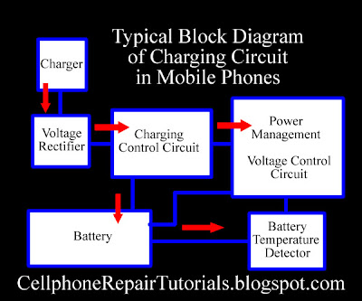 A charging circuit is composed of the following stages or sections. 1. Battery Charger Circuits - Although this is not found on mobile phones PC board circuit and have separate circuit but definitely this is also part of charging circuit; without this, the charging circuit is not complete and will not work completely. This circuit is all parts and components that being mounted on any mobile phone charger, this is the one that converts AC (Alternating Current)voltage to DC (Direct Current)voltage. What is AC Voltage? This voltage is a power source that we used in our household appliances to work and operate, this voltage can cause risk of electric shock and very dangerous to humans when being touch.This kind of voltage has an alternate polarity. What is DC voltage? This voltage is a low level voltage which typically found on any kind of batteries. This kind of voltage have two polarities, the negative and the positive. Here's how the battery charger works, the 110 or 220 AC volts coming from the electrical outlet at home or etc. will be converted to a desired DC voltage like 4.5 to 6 volt DC because the phone only accepts and can be operated into small amount of DC voltage.  A DC voltage output of a charger is only an artificial DC voltage, why is that? because only a battery cell can produce a 100% pure DC voltage. 2. Protection Circuit- this circuit is composed of a Fuse, Inductor coil Diode and Capacitors, before the DC voltage reach to the charging voltage control circuits the protection circuit is the one that control and check if that voltage is in exact amount. Let say the desired amount of DC voltage is only 5.6 volts above that point the fuse will be blown out to stop the voltage to flow so that it prevents damaging to another corresponding circuits. In a protection circuit below of Nokia BB5 mobile phones a diode is the one that measure the amount of voltage from the battery charger, this diode has a reaching point of desired voltage to measure of how much amount of voltage will be allowed to flow within that line, when exceed to that desired point of voltage the diode will then cut it off. 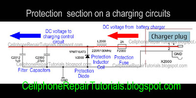 like for example if that diode is being designed that only allows only 7 volts from the battery charger to flow on that line. Now, above that desired voltage let say that the voltage becomes 8 or higher the diode will then be reacts and destruct itself, this is what then so-called shorted component; so that the current will flow directly to ground and will not reach to the following or corresponding circuit. If the diode will cut off or shorted the fuse will tends to blow and totally cut the voltage line. The inductor coil's role is to filter unwanted voltage saturation, it rejects abnormal voltage modulation caused by electrostatic interference. 3. Charger Voltage Control Circuit - This is the stage where the charger voltage and current is being stabilized, amplified, rectified, regulated and other voltage purification process is being held in this area before it feeds to the battery. This kind of circuit commonly being pack in a chips together with another circuits. A failure of this certain area will result on charging problem status. This area mostly called by most technician as a Charging IC it is because this circuit is inside in a particular IC chips, but eventually this circuit also accompanied by many other circuit types and not exclusive to a certain charging area. 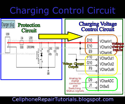 This pictures shows is the next corresponding circuit from the protection circuit area. The voltage from charger is now then feeds into three terminal inputs of the charger voltage control circuits.  n this figure shows after the voltage stabilization and purification process the voltage is now then feeds to the battery terminal. 4. Charging Control Circuit - this is the area where the charging process is being monitored, this is the one that sends information to the application processor to start or stop the charging process. This area is part of Power management circuit, so-called POWER IC by many technicians. http://1.bp.blogspot.com/_8JZhVVmpICU/S-lrokgdQaI/AAAAAAAAAWA/zfjyOT1UwXI/s400/chargistatcircuit.jpgIn this picture that there are two terminal signal from the voltage control that sends data to the Charging control circuit, this two data signals will inform to the charging control circuit that a charger voltage is being entered or plug-in. After this charging control circuits receives the data it will then analyze and convert that data into digital signal then sends it to the Application processor.  The application processor which is the brain of all the circuits now then decide if all the data's are in correct or in right information to begin the process, It always relies on the data that sends by the charging control circuit, then decide all data and completely process it. Okay now lets take an example and apply this particular method on a mobile phone circuitry component layout, I have here a Nokia N95 board, which is a good way to start with, while we still working on advance training. Now, try to analyze and compare all of those previous picture above and combined them into each corresponding stages or section, in this manner you can build an step by step tracing procedure on how to deal charging problem issues. 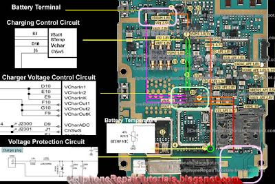  | |
| | | | FULLFLASHGSM
THE GREAT ADMIN
Age : 42
Job/hobbies : www.apptekgsm.com
| | Subject: Re: Sticky: Collection Mobile Tips & Tricks Sun Sep 26, 2010 5:01 pm | |
| Understanding how RF circuit Works on Cell Phones In cell phone repair it is very helpful to understand how the RF circuits works , for this is a big help when troubleshooting No signal problem issues. RF stands for radio frequency , this frequency is used to transmit and receive the data signals from a mobile phone. Here's a brief explanation on how does RF circuit works on mobile phones. This is for GSM RF circuit only, although the WCDMA circuit and WI-FI circuit have similarity on this but I will try to explain both of it hereafter. See the block diagram below. Observe how the frequency data signal feeds from a certain parts of an RF circuit design. A breakdown or failure of each certain part will result to signal loss and the capability to generate, amplify, control , process, send and receive the desired radio frequency during transmission process.  In mobile phones transmission there are two types of operation took place, the receiving operation and the transmitting operation. In normal mode, RX part is always active in receiving operation the antenna switch is always open its gateway through to the RX circuit, It is always ready to receive and intercepts the radio waves and wait for the desired frequency signal to catch up. During transmission like making a call or sending a text message the antenna switch will close the gateway of the RX and open the gateway of the TX in order not to interfere the data signal during transmission. All data that has been receive and before to transmit or send, all this data signals are feeds to the baseband processor. An explanation of an RF Circuit Parts and what possible problems if a certain part is damaged. RF Receiver - ( RX radio receiver ) The rf receiver are called RX, this circuit is design to receives, and process the data signals from the airwaves during transmission process. A failure of this circuit will result to unable to receive data signal during transmission. RF Transmitter - ( TX radio transmitter ) the rf transmitter are called TX which is the one that process, amplify the data signals from a mobile phone . Once failed to initiate a failure to transmit radio frequency signal, this will result to unable to send data signal during transmission. . Power amplifier - RF amplifier The power amplifier is used to amplify, boost up the radio frequency signal before it feeds to the antenna before it thrown over the air waves during transmission. If damaged will result to signal loss. The Antenna is used to intercepts and thrown the radio radio frequency in the air during transmission When electricity is "thrown" into the metal of an antenna, the metal reacts to the electricity at an atomic level in the form of a wave. if damaged or due to a corroded terminal pads, will indicate a show a poor signal or low level frequency signal. Antenna switch The antenna switch is used as a gateway that controls and manage the frequency to pass through, it switch the RX frequency signal and TX frequency signal during transmission process. literally the antenna is the signal catcher and likewise the signal thrower. If damaged the gateway to the antenna will be closed and result to network signal indication. Crystal oscillator Generates a desired frequency that feeds to the RX and TX circuits. In mobile phones a Voltage controlled Oscillator (VCO) and Voltage Controlled Temperature Compensated Crystal Oscillator (VCTXO) is used in rf circuit. If damaged the RX and TX will not work and the RF cicuit is at full failure. SAW filter Surface Acoustic Wave filter used as an rf synthesizer to purify a desired level of frequency. If damaged result also to no network signal indication. An example of the RF circuit components layout on a PCB board. 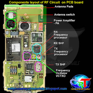 The rf circuit components are often covered with shielding metal case unlike the baseband processor parts which is oftentimes not. This is because frequency is very vulnerable with unwanted radio waves interference and destroys data signals. Using the shielding metal will minimize the radio waves interference. | |
| | | | FULLFLASHGSM
THE GREAT ADMIN
Age : 42
Job/hobbies : www.apptekgsm.com
| | Subject: Re: Sticky: Collection Mobile Tips & Tricks Sun Sep 26, 2010 5:23 pm | |
| How To Use and Read a Multimeter
Using a multimeter is quite bit difficult for the first time especially the analog type one unlike the digital which is more convenient to use for beginners. Every multimeter have its own user manual accompanied when you purchased it at any electronics store in your areas, and each one varies on how each circuits designed but there's always only one thing in common, a Multimeter is is used to measure voltages AC or DC, currents and resistance, continuity and electronics components. Maybe this only a take brief explanation on how to use a multimeter, I have an example copy around here using my Sanwa analog multimeter which is made from Japan. PARTS OF A MULTIMETER
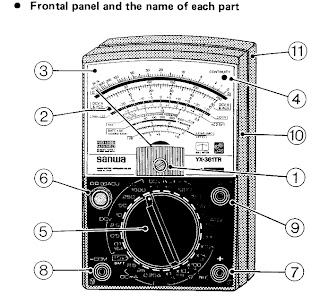 1.) Indicator Zero Connector 7.) Measuring Terminal + 2.) Indicatot Pointer 8.) Measurin Terminal - COM 3.) Indicator Scale 9.) Series Terminal Capacitor OUTPUT 4.) Continuity Indicating 10.) Panel LED ( CONTINUITY ) 11.) Rear Case 5.) Range Selector Switch knob 6.) 0-ohms adjusting knob /0- centering meter (NULL meter) adjusting knob EXPLANATION ABOUT THE SCALE
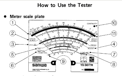 1.) Resistance - Singlaji Deepak | +91-9354267000 | singlaji@ymail.com | gmail@singlaji.com | singlaji@live.com -(OHMS) scale 2.) DCV, A scale and ACV scale (10V or more) 3.) 0-centerig (NULL) +/- DCV scale 4.) ACV 2.5 (AC 2.5V) exclusive scale 5.) Transistor DC amplification factor (hFE) scale 6.) 1.5 baterry test (BATT 1.5V) 7.) OHMS range terminal to terminal current (Li) scale) 8.) OHMS range terminal to terminal voltage (LV) scale 9.) Decibel (dB) scale 10.) Continuity Indicating LED 11.0 Mirror: To obtain most accurate readings, the mirror is deviced to make operator eyes, the indicator pointer, and the indicator pointer reflexed to the mirror put together in line. How to Measure Resistance Multimeter with selector set to "Ohms". This meter only has a single Ohms range.Multimeter with selector set to "Ohms". This meter only has a single Ohms range. Set the multimeter to Ohms or Resistance (turn meter on if it has a separate power switch). Understand that resistance and continuity are opposites. The multimeter measures resistance in ohms, it can not measure continuity. When there is little resistance there is a great deal of continuity. Conversely, when there is a great deal of resistance, there is little continuity. With this in mind, when we measure resistance we can make assumptions about continuity based on the resistance values measured. Observe the meter indication. If the test leads are not in contact with anything, the needle or pointer of an analog meter will be resting at the left most position. This is represents an infinite amount of resistance, or an "open circuit"; it is also safe to say there is the no continuity, or path between the black and red probes. Careful inspection of the dial should reveal the OHM scale. It is usually the top-most scale and has values that are highest on the left of the dial (a sideways "8" for infinity) and gradually reduce to 0 on the right. This is opposite of the other scales; they have the lowest values on the left and increase going right. Connect the black test lead to the jack marked "Common" or "-" Connect the red test lead to the jack marked with the Omega (Ohm symbol) or letter "R" near it. Set the range (if provided) to R x 100. Hold the probes at the end of the test leads together. The meter pointer should move fully to the right. Locate the "Zero Adjust" knob and rotate so that the the meter indicates "0" (or as close to "0" as possible). Note that this position is the "short circuit" or "zero ohms" indication for this R x 1 range of this meter. Always remember to "zero" the meter immediately after changing resistance ranges. Replace batteries if needed. If unable to obtain a zero ohm indication, this may mean the batteries are weak and should be replaced. Retry the zeroing step above again with fresh batteries. Measure resistance of something like a known-good lightbulb. Locate the two electrical contact points of the bulb. They will be the threaded base and the center of the bottom of the base. Have a helper hold the bulb by the glass only. Press the black probe against the threaded base and the red probe against the center tab on the bottom of the base. Watch the needle move from resting at the left and move quickly to 0 on the right. Change the range of the meter to R x 1. Zero the meter again for this range. Repeat the step above. Observe how the meter did not go as far to the right as before. The scale of resistance has been changed so that each number on the R scale can be read directly. In the previous step, each number represented a value that was 100 times greater. Thus, 150 really was 15,000 before. Now, 150 is just 150. Had the R x 10 scale been selected, 150 would have been 1,500. The scale selected is very important for accurate measurements. With this understanding, study the R scale. It is not linear like the other scales. Values at the left side are harder to accurately read than those on the right. Trying to read 5 ohms on the meter while in the R x 100 range would look like 0. It would be much easier at the R x 1 scale instead. This is why when testing resistance, adjust the range so that the readings may be taken from the middle rather than the extreme left or right sides. Test resistance between hands. Set the meter to the highest R x value possible. Zero the meter. Loosely hold a probe in each hand and read the meter. Squeeze both probes tightly. Notice the resistance is reduced. Let go of the probes and wet your hands. Hold the probes again. Notice that the resistance is lower still. For these reasons, it is very important that the probes not touch anything other than the device under test. A device that has burned out will not show "open" on the meter when testing if your fingers provide an alternate path around the device, like when they are touching the probes. Testing round cartridge type and older style glass automotive fuses will indicate low values of resistance if the fuse is lying on a metal surface when under test. The meter indicates the resistance of the metal surface that the fuse is resting upon (providing an alternate path between the red and black probe around the fuse) instead of trying to determine resistance through the fuse. Every fuse, good or bad, will indicate "good". How to Measure Voltage Set the meter for the highest range provided for AC Volts. Many times, the voltage to be measured has a value that is unknown. For this reason, the highest range possible is selected so that the meter circuitry and movement will not be damaged by voltage greater than expected. If the meter were set to the 50 volt range and a common U.S. electrical outlet were to be tested, the 120 volts present could irreparably damage the meter. Start high, and work downward to the lowest range that can be safely displayed. Insert the black probe in the "COM" or "-" jack. Insert the red probe in the "V" or "+" jack. Locate the Voltage scales. There may be several Volt scales with different maximum values. The range chosen the selector knob determines which voltage scale to read. The maximum value scale should coincide with selector knob ranges. The voltage scales, unlike the Ohm scales, are linear. The scale is accurate anywhere along its length. It will of course be much easier accurately reading 24 volts on a 50 volt scale than on a 250 volt scale, where it might look like it is anywhere between 20 and 30 volts. Test a common electrical outlet. In the U.S. you might expect 120 volts or even 240 volts. In other places, 240 or 380 volts might be expected. Press the black probe into one of the straight slots. It should be possible to let go of the black probe, as the contacts behind the face of the outlet should grip the probe, much like it does when a plug is inserted. Insert the red probe into the other straight slot. The meter should indicate a voltage very close to 120 or 240 volts (depending on type outlet tested). Remove the probes, and rotate the selector knob to the lowest range offered, that is greater than the voltage indicated (120 or 240). Reinsert the probes again as described earlier. The meter may indicate between 110 and as much as 125 volts this time. The range of the meter is important to obtain accurate measurements. If the pointer did not move, it is likely that DC was chosen instead of AC. The AC and DC modes are not compatible. The correct mode MUST be set. If not set correctly, the user would mistakenly believe there was no voltage present. This could be deadly. Be sure to try BOTH modes if the pointer does not move. Set meter to AC volts mode, and try again. Whenever possible, try to connect at least one probe in such a way that it will not be required to hold both while making tests. Some meters have accessories that include alligator clips or other types of clamps that will assist doing this. Minimizing your contact with electrical circuits drastically reduces that chances of sustaining burns or injury. How to Measure Current Amperes Determine if AC or DC by measuring the voltage of the circuit as outlined above. Set the meter to the highest AC or DC Amp range supported. If the circuit to be tested is AC but the meter will only measure DC amps (or vice-versa), stop. The meter must be able to measure the same mode (AC or DC) Amps as the voltage in the circuit, otherwise it will indicate 0. Be aware that most multimeters will only measure extremely small amounts of current, in the uA and mA ranges. 1 uA is .000001 amp and 1 mA is .001 amp. These are values of current that flow only in the most delicate electronic circuits, and are literally thousands (and even millions) of times smaller than values seen in the home and automotive circuits that most homeowners would be interested testing. Just for reference, a typical 100W / 120V light bulb will draw .833 Amps. This amount of current would likely damage the meter beyond repair. A "clamp-on" type ammeter would be ideal for the typical homeowner requirements, and does not require opening the circuit to take measurements (see below). If this meter were to be used to measure current through a 4700 ohm resistor across 9 Volts DC, it would be done as outlined below: Insert the black probe into the "COM" or "-" jack. Insert the red probe into the "A" jack. Shut off power to the circuit. Open the portion of the circuit that is to be tested (one lead or the other of the resistor). Insert the meter in series with the circuit such that it completes the circuit. An ammeter is placed IN SERIES with the circuit to measure current. It cannot be placed "across" the circuit the way a voltmeter is used (otherwise the meter will probably be damaged). Polarity must be observed. Current flows from the positive side to the negative side. Set the range of current to the highest value. Apply power and adjust range of meter downward to allow accurate reading of pointer on the dial. Do not exceed the range of the meter, otherwise it may be damaged. A reading of about 2 milliamps should be indicated since from Ohm's law I = V / R = (9 volts)/(4700 Ω) = .00191 amps = 1.91 mA. If you're measuring the current consumed by the device itself, be aware of any filter capacitors or any element that requires an inrush (surge) current when switched on. Even if the operating current is low and within the range of the meter fuse, the surge can be MANY times higher than the operating current (as the empty filter capacitors are almost like a short circuit). Blowing the meter fuse is almost certain if the DUT's (device under test) inrush current is many times higher than the fuses rating. In any case, always use the higher range measurement protected by the higher fuse rating (if your meter has two fuses), or just be careful. | |
| | | | FULLFLASHGSM
THE GREAT ADMIN
Age : 42
Job/hobbies : www.apptekgsm.com
| | Subject: Re: Sticky: Collection Mobile Tips & Tricks Sun Sep 26, 2010 5:28 pm | |
| | |
| | | | FULLFLASHGSM
THE GREAT ADMIN
Age : 42
Job/hobbies : www.apptekgsm.com
| | Subject: Re: Sticky: Collection Mobile Tips & Tricks Sun Sep 26, 2010 5:31 pm | |
| | |
| | | | FULLFLASHGSM
THE GREAT ADMIN
Age : 42
Job/hobbies : www.apptekgsm.com
| | Subject: Re: Sticky: Collection Mobile Tips & Tricks Sun Sep 26, 2010 7:05 pm | |
| How To Use and Read a Multimeter
Using a multimeter is quite bit difficult for the first time especially the analog type one unlike the digital which is more convenient to use for beginners. Every multimeter have its own user manual accompanied when you purchased it at any electronics store in your areas, and each one varies on how each circuits designed but there's always only one thing in common, a Multimeter is is used to measure voltages AC or DC, currents and resistance, continuity and electronics components. Maybe this only a take brief explanation on how to use a multimeter, I have an example copy around here using my Sanwa analog multimeter which is made from Japan. PARTS OF A MULTIMETER
1.) Indicator Zero Connector 7.) Measuring Terminal + 2.) Indicatot Pointer 8.) Measurin Terminal - COM 3.) Indicator Scale 9.) Series Terminal Capacitor OUTPUT 4.) Continuity Indicating 10.) Panel LED ( CONTINUITY ) 11.) Rear Case 5.) Range Selector Switch knob 6.) 0-ohms adjusting knob /0- centering meter (NULL meter) adjusting knob EXPLANATION ABOUT THE SCALE1.) Resistance - -(OHMS) scale 2.) DCV, A scale and ACV scale (10V or more) 3.) 0-centerig (NULL) +/- DCV scale 4.) ACV 2.5 (AC 2.5V) exclusive scale 5.) Transistor DC amplification factor (hFE) scale 6.) 1.5 baterry test (BATT 1.5V) 7.) OHMS range terminal to terminal current (Li) scale) 8.) OHMS range terminal to terminal voltage (LV) scale 9.) Decibel (dB) scale 10.) Continuity Indicating LED 11.0 Mirror: To obtain most accurate readings, the mirror is deviced to make operator eyes, the indicator pointer, and the indicator pointer reflexed to the mirror put together in line. How to Measure Resistance Multimeter with selector set to "Ohms". This meter only has a single Ohms range.Multimeter with selector set to "Ohms". This meter only has a single Ohms range. Set the multimeter to Ohms or Resistance (turn meter on if it has a separate power switch). Understand that resistance and continuity are opposites. The multimeter measures resistance in ohms, it can not measure continuity. When there is little resistance there is a great deal of continuity. Conversely, when there is a great deal of resistance, there is little continuity. With this in mind, when we measure resistance we can make assumptions about continuity based on the resistance values measured. Observe the meter indication. If the test leads are not in contact with anything, the needle or pointer of an analog meter will be resting at the left most position. This is represents an infinite amount of resistance, or an "open circuit"; it is also safe to say there is the no continuity, or path between the black and red probes. Careful inspection of the dial should reveal the OHM scale. It is usually the top-most scale and has values that are highest on the left of the dial (a sideways "8" for infinity) and gradually reduce to 0 on the right. This is opposite of the other scales; they have the lowest values on the left and increase going right. Connect the black test lead to the jack marked "Common" or "-" Connect the red test lead to the jack marked with the Omega (Ohm symbol) or letter "R" near it. Set the range (if provided) to R x 100. Hold the probes at the end of the test leads together. The meter pointer should move fully to the right. Locate the "Zero Adjust" knob and rotate so that the the meter indicates "0" (or as close to "0" as possible). Note that this position is the "short circuit" or "zero ohms" indication for this R x 1 range of this meter. Always remember to "zero" the meter immediately after changing resistance ranges. Replace batteries if needed. If unable to obtain a zero ohm indication, this may mean the batteries are weak and should be replaced. Retry the zeroing step above again with fresh batteries. Measure resistance of something like a known-good lightbulb. Locate the two electrical contact points of the bulb. They will be the threaded base and the center of the bottom of the base. Have a helper hold the bulb by the glass only. Press the black probe against the threaded base and the red probe against the center tab on the bottom of the base. Watch the needle move from resting at the left and move quickly to 0 on the right. Change the range of the meter to R x 1. Zero the meter again for this range. Repeat the step above. Observe how the meter did not go as far to the right as before. The scale of resistance has been changed so that each number on the R scale can be read directly. In the previous step, each number represented a value that was 100 times greater. Thus, 150 really was 15,000 before. Now, 150 is just 150. Had the R x 10 scale been selected, 150 would have been 1,500. The scale selected is very important for accurate measurements. With this understanding, study the R scale. It is not linear like the other scales. Values at the left side are harder to accurately read than those on the right. Trying to read 5 ohms on the meter while in the R x 100 range would look like 0. It would be much easier at the R x 1 scale instead. This is why when testing resistance, adjust the range so that the readings may be taken from the middle rather than the extreme left or right sides. Test resistance between hands. Set the meter to the highest R x value possible. Zero the meter. Loosely hold a probe in each hand and read the meter. Squeeze both probes tightly. Notice the resistance is reduced. Let go of the probes and wet your hands. Hold the probes again. Notice that the resistance is lower still. For these reasons, it is very important that the probes not touch anything other than the device under test. A device that has burned out will not show "open" on the meter when testing if your fingers provide an alternate path around the device, like when they are touching the probes. Testing round cartridge type and older style glass automotive fuses will indicate low values of resistance if the fuse is lying on a metal surface when under test. The meter indicates the resistance of the metal surface that the fuse is resting upon (providing an alternate path between the red and black probe around the fuse) instead of trying to determine resistance through the fuse. Every fuse, good or bad, will indicate "good". How to Measure Voltage Set the meter for the highest range provided for AC Volts. Many times, the voltage to be measured has a value that is unknown. For this reason, the highest range possible is selected so that the meter circuitry and movement will not be damaged by voltage greater than expected. If the meter were set to the 50 volt range and a common U.S. electrical outlet were to be tested, the 120 volts present could irreparably damage the meter. Start high, and work downward to the lowest range that can be safely displayed. Insert the black probe in the "COM" or "-" jack. Insert the red probe in the "V" or "+" jack. Locate the Voltage scales. There may be several Volt scales with different maximum values. The range chosen the selector knob determines which voltage scale to read. The maximum value scale should coincide with selector knob ranges. The voltage scales, unlike the Ohm scales, are linear. The scale is accurate anywhere along its length. It will of course be much easier accurately reading 24 volts on a 50 volt scale than on a 250 volt scale, where it might look like it is anywhere between 20 and 30 volts. Test a common electrical outlet. In the U.S. you might expect 120 volts or even 240 volts. In other places, 240 or 380 volts might be expected. Press the black probe into one of the straight slots. It should be possible to let go of the black probe, as the contacts behind the face of the outlet should grip the probe, much like it does when a plug is inserted. Insert the red probe into the other straight slot. The meter should indicate a voltage very close to 120 or 240 volts (depending on type outlet tested). Remove the probes, and rotate the selector knob to the lowest range offered, that is greater than the voltage indicated (120 or 240). Reinsert the probes again as described earlier. The meter may indicate between 110 and as much as 125 volts this time. The range of the meter is important to obtain accurate measurements. If the pointer did not move, it is likely that DC was chosen instead of AC. The AC and DC modes are not compatible. The correct mode MUST be set. If not set correctly, the user would mistakenly believe there was no voltage present. This could be deadly. Be sure to try BOTH modes if the pointer does not move. Set meter to AC volts mode, and try again. Whenever possible, try to connect at least one probe in such a way that it will not be required to hold both while making tests. Some meters have accessories that include alligator clips or other types of clamps that will assist doing this. Minimizing your contact with electrical circuits drastically reduces that chances of sustaining burns or injury. How to Measure Current Amperes Determine if AC or DC by measuring the voltage of the circuit as outlined above. Set the meter to the highest AC or DC Amp range supported. If the circuit to be tested is AC but the meter will only measure DC amps (or vice-versa), stop. The meter must be able to measure the same mode (AC or DC) Amps as the voltage in the circuit, otherwise it will indicate 0. Be aware that most multimeters will only measure extremely small amounts of current, in the uA and mA ranges. 1 uA is .000001 amp and 1 mA is .001 amp. These are values of current that flow only in the most delicate electronic circuits, and are literally thousands (and even millions) of times smaller than values seen in the home and automotive circuits that most homeowners would be interested testing. Just for reference, a typical 100W / 120V light bulb will draw .833 Amps. This amount of current would likely damage the meter beyond repair. A "clamp-on" type ammeter would be ideal for the typical homeowner requirements, and does not require opening the circuit to take measurements (see below). If this meter were to be used to measure current through a 4700 ohm resistor across 9 Volts DC, it would be done as outlined below: Insert the black probe into the "COM" or "-" jack. Insert the red probe into the "A" jack. Shut off power to the circuit. Open the portion of the circuit that is to be tested (one lead or the other of the resistor). Insert the meter in series with the circuit such that it completes the circuit. An ammeter is placed IN SERIES with the circuit to measure current. It cannot be placed "across" the circuit the way a voltmeter is used (otherwise the meter will probably be damaged). Polarity must be observed. Current flows from the positive side to the negative side. Set the range of current to the highest value. Apply power and adjust range of meter downward to allow accurate reading of pointer on the dial. Do not exceed the range of the meter, otherwise it may be damaged. A reading of about 2 milliamps should be indicated since from Ohm's law I = V / R = (9 volts)/(4700 Ω) = .00191 amps = 1.91 mA. If you're measuring the current consumed by the device itself, be aware of any filter capacitors or any element that requires an inrush (surge) current when switched on. Even if the operating current is low and within the range of the meter fuse, the surge can be MANY times higher than the operating current (as the empty filter capacitors are almost like a short circuit). Blowing the meter fuse is almost certain if the DUT's (device under test) inrush current is many times higher than the fuses rating. In any case, always use the higher range measurement protected by the higher fuse rating (if your meter has two fuses), or just be careful. | |
| | | | FULLFLASHGSM
THE GREAT ADMIN
Age : 42
Job/hobbies : www.apptekgsm.com
| | Subject: Re: Sticky: Collection Mobile Tips & Tricks Sun Sep 26, 2010 7:10 pm | |
| | |
| | | | FULLFLASHGSM
THE GREAT ADMIN
Age : 42
Job/hobbies : www.apptekgsm.com
| | Subject: Re: Sticky: Collection Mobile Tips & Tricks Sun Sep 26, 2010 7:13 pm | |
| | |
| | | | FULLFLASHGSM
THE GREAT ADMIN
Age : 42
Job/hobbies : www.apptekgsm.com
| | Subject: Re: Sticky: Collection Mobile Tips & Tricks Sun Sep 26, 2010 7:17 pm | |
| How Do SIM Card Works on Mobile Phones Circuit
A SIM Card also known as Subscriber Identity Module, A SIM is a Smart Card that can store data from a cellular phone. Those data like identity, location and phone number, network authorization data, personal security keys, contact lists and stored text messages. Security features include authentication and encryption to protect data and prevent eavesdropping.
But how does this SIM card works within the mobile phones circuit? How does mobile phones reads and write data unto it?
In those particular questions above, If we learn answers unto it, we can solve problem issues regarding SIM related problems, like Insert Sim Card and etc.
Now here's a brief explanation on how does SIM Circuit Works on a mobile phones circuit.
A Sim Card have six pads that also corresponds to the six SIM connectors pins, but only five has totally have connection on the entire layout.
SIM DATA - this is a digital data that being stored on a SIM memory
SIM Clock - this is a clock frequency signal that being synchronize to the digital data to create data signal in order transfer or sends and receive data information.
SIM Reset - this is also a frequency signal that triggers or reset all synchronization process.
VSIM B+ Supply Voltage- This a power supply voltage used to activated the SIM circuit.
SIM Ground - a ground line voltage
The other one is not connected
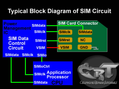 A Typical block Diagram above shows on how SIM Circuit Works on a Cellular phones circuits. A Typical block Diagram above shows on how SIM Circuit Works on a Cellular phones circuits.
In the layout the Sim Interface Connector connected directly to SIM Control Circuit. The SIM Control Circuit is the one the generates Clock frequency that triggers the SIM data storage, once the SIM is now being triggered, it is then now sends data information to the application processor to begin the process with. The application processor is the one that gathered all data information from the SIM memory, initiate and activate it, if all information is in desired status.
Those three particular lines of signal flows associated in the circuit shows how the synchronization is being applied. If one of those lines being cut off the sending and receiving process will breakdown, and will result to SIM problem issues. The Power Supply Voltage through the SIM is also remain stable otherwise a lack of voltage will not activate the SIM to work.
 In a picture below an EMI-ESD Filter has been added to protect the circuit to an Electro-static Discharge and Electro-magnetic Interference disorders. This type of SIM connection circuit is an advantage to mobile phone technician for troubleshooting SIM related problem issues. Thus, type of particular EMI filter is very vulnerable and mostly create breakdown to the entire SIM connection. In a picture below an EMI-ESD Filter has been added to protect the circuit to an Electro-static Discharge and Electro-magnetic Interference disorders. This type of SIM connection circuit is an advantage to mobile phone technician for troubleshooting SIM related problem issues. Thus, type of particular EMI filter is very vulnerable and mostly create breakdown to the entire SIM connection.
 The picture below is an equivalent layout of an EMI filter and its internal circuitry, The picture below is an equivalent layout of an EMI filter and its internal circuitry,
only both frequency and data lines is being filtered.
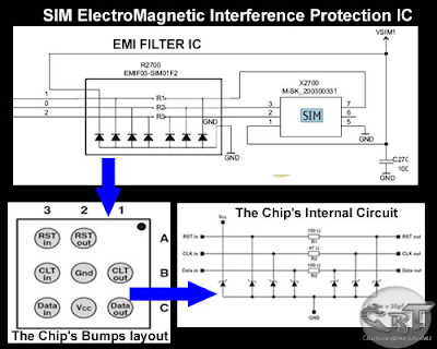 The EMI Filter is a tiny chips designed to protect SIM DATA, SIM Clock and SIM Reset data signals that flow across trough the SIM connector. 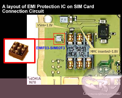 The EMI-ESD Filter is a highly integrated device designed to suppress EMI(Electromagnetic Interference) and RFI(Radio frequency Interference in a circuit. This filter includes ESD protection circuitry which prevents damaging the mobile phone application when subject to ESD ( ElectroStatic Discharge) surges up to 15 kV. The EMI-ESD Filter is a highly integrated device designed to suppress EMI(Electromagnetic Interference) and RFI(Radio frequency Interference in a circuit. This filter includes ESD protection circuitry which prevents damaging the mobile phone application when subject to ESD ( ElectroStatic Discharge) surges up to 15 kV.
Here's an example of how the the SIM data signal flow across the printed circuit board. Note: this is only shows where the signal flows from component to component connections. 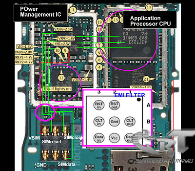 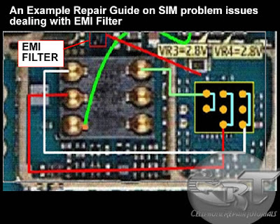 A picture above is an alternative way by many mobile phone technician dealing with SIM problem issues on most Nokia Mobile Phones. A picture above is an alternative way by many mobile phone technician dealing with SIM problem issues on most Nokia Mobile Phones. | |
| | | | FULLFLASHGSM
THE GREAT ADMIN
Age : 42
Job/hobbies : www.apptekgsm.com
| | Subject: Re: Sticky: Collection Mobile Tips & Tricks Sun Sep 26, 2010 7:20 pm | |
| Basic GSM abbreviations and acronyms
GSM - Global System for Mobile Communications
GPRS - General Packet Radio Service
CDMA - Code division multiple access
W-CDMA - Wideband Code Division Multiple Access
SIM - subscriber identity module
WAP - Wireless Application Protocol
SMS Short Messaging System
3G (or 3-G) - is short for third-generation technology.
Other technical terms:
IC - Intergrated Circuit
UEM - Universal Energy Module
PPM - Phone Permanent Memory
MCU - Micro Controller Unit
PM - Permanent Memory
COBBA IC - Common Base Band Analog (as per Hitek's knowledge)
How About this?
UFS- Universal Flasher Software
JAF - Just Another Flasher
Parts Acronyms
--------------------------------------------------------------------------------
EEPROM - Electronically Erasable Programmable Memory
UEM - Universal Energy Management
UPP - Universal Phone Programmer
RAM - Random Access Memory
SRAM - Syncronous Random Access Memory
COBBA- Common Baseband Analog
CCONT- Current CONTroller
MAD - Memory Analog Digital
and also the extensions...
MCU - Micro Control Unit
PP- Product Profile
PM- Permanent Memory
CNT- Content
VCO.................Voltage Control Oscillator
DSP.................Digital Signal Processor
BGA.................Ball Grid Array
EEPROM...........Electronically Erasable Programmable ROM
some more glossary...
ACCH (Analog Control Channel)
AMPS (Advanced Mobile Phone Service)
ASIC (Application Specific Integrated Circuit)
Electronic chips designed for some concrete purposes (for example, in phone it controlls communication between MCU and DSP) They're designed and produced by the companies which use them.
AVCH (Analog Voice Channel)
BCC (Base-station Color Code)
BSC (Base Station Controller)
BSIC (Base Station Identity Code or Base transceiver Station Identity Code)
BTS (Base Transceiver Station)
This device allows communication between phones and cellular network
C1 (path loss-criterium)
RX
Strength of signal received
RxLevAm (Rx Level Access minimum)
MSTxPwr
Max power, which can be transmitted by phone to get access
MSMaxTxPwr
Max permissible transmission power of the phone
C2 (cell-reselection criterion)
CDMA (Code Division Multiple Access; also known as IS-95)
One of the newer digital technologies in 800 or 1900 Mhz. Used in North America, Australia and some southeastern Asian countries (e.g. Hong Kong and South Korea). It doesn't divide the radio frequency spectrum into separate user channels by frequency slices or time slots, but separates users by assigning them digital codes within the same broad spectrum.
DCCH (Digital Control Channel)
DTCH (Digital Traffic Channel)
DTX (Discontinous Transmission Exchange)
FDMA (Frequency Division Multiple Access)
This name means multiaccess on frequency field: transmission proceeds on different frequencies at the same time (this is a "full duplex" connection): there is - from the phone to BTS (this is called "up" and "down" because BTS antennas are usually higher than phone ones, so the signal from BTS to the phone really must go down (and vice versa)).
GSM (Global System for Mobile Communication)
Cellular telecommunication system working at 900 MHz. It also has a 1800 MHz (DCS) and 1900 MHz (PCS) version
HLR (Home Location Register
IMEI (International Mobile Equipment Identification code)
IMSI (International Mobile Subscriber Identify)
MSC (Mobile Switching Center)
NCC (National Color Code or Network Color Code)
PLMN (Public Land Mobile Network)
PLU (Periodic Location Update)
TCH (Traffic Channels)
HR (Half Rate Traffic)
FR (Full Rate Traffic)
EFR (Enhanced Full Rate)
TDMA (Time Division Multiple Access)
This means multiaccess in time: several phones can transmit signal (either digitized voice or computer data) in the same time on the same channel
TMSI (Temporary Mobile Subscriber Identity)
VLR (Visitor Location Register)
SRAM- syncronous random access memory tama ba ko?
MCU -micro control unit
1G
The first generation of analogue mobile phone technologies including AMPS, TACS and NMT
2G
The second generation of digital mobile phone technologies including GSM, CDMA IS-95 and D-AMPS IS-136
2.5G
The enhancement of GSM which includes technologies such as GPRS
3G
The third generation of mobile phone technologies covered by the ITU IMT-2000 family
3GPP
The 3rd Generation Partnership Project, a grouping of international standards bodies, operators and vendors with the responsibility of standardising the WCDMA based members of the IMT-2000 family
3GPP2
The counterpart of 3GPP with responsibility for standardising the CDMA2000-based members of the IMT-2000 family. 3GPP2 is spearheaded by ANSI
8PSK
Octantal Phase Shift Keying
A5/1/2/3/8X
Encryption algorithms for GSM networks
AAL
ATM Adaptation Layer
ABR
Available Bit Rate
A-bis
Interface between the BSC and BTS in a GSM network
AB
Access Burst; used for random access and characterised by a longer guard period to allow for burst transmission from a MS that does not know the correct timing advance when first contacting a network
ACTE
Approvals Committee for Terminal Equipment
ACTS
Advanced Communications Technologies and Services a European technology initiative
ACU
Antenna Combining Unit
ADPCM
Adaptive Differential Pulse Code Modulation; a form of voice compression that typically uses 32kbit/s
AFC
Automatic Frequency Control
AGCH
Access Grant Channel; downlink only, BTS allocates a TCH or SDCCH to the MS, allowing it access to the network
Air interface
In a mobile phone network, the radio transmission path between the base station and the mobile terminal
A-interface
Interface between the MSC and BSS in a GSM network
AM
Amplitude Modulation
AMPS
Advanced Mobile Phone System, the analogue mobile phone technology used in North and South America and in around 35 other countries. Operates in the 800MHz band using FDMA technology
AMR
Adaptive Multi-Rate codec. Developed in 1999 for use in GSM networks, the AMR
has been adopted by 3GPP for 3G
Analogue
The representation of information by a continuously variable physical quantity such as voltage
ANSI
American National Standards Institute. An non-profit making US organisation which does not carry out standardisation work but reviews the work of standards bodies and assigns them category codes and numbers
ANSI-136
See D-AMPS
API
Application Program Interface
AoC
Advice of Charge
ARIB
Association of Radio Industries and Businesses. An organisation established by Japan Ministry of Posts and Communications to act as the standardisation authority for radio communication and broadcasting
ARPU
Average Revenue Per User
ASCII
American Standard Code for Information Interchange
ASIC
Application Specific Integrated Circuit
ASP
Application Service Provider
Asymmetric Transmission
Data transmissions where the traffic from the network to the subscriber is at a higher rate than the traffic from the subscriber to the network
A-TDMA
Advanced Time Division Multiple Access
ATM
Asynchronous Transfer Mode; a multiplexed information transfer and switching method in which the data is organised into fixed length 53-octet cells and transmitted according to each application instantaneous need
AUC
Authentication Centre; the element within a GSM network which generates the parameters for subscriber authentication
Bandwidth
A term meaning both the width of a transmission channel in terms of Hertz and the maximum transmission speed in bits per second that it will support
BCH
Broadcast Channels; carry only downlink information and are mainly responsible for synchronisation and frequency correction (BCCH, FCCH and SCH)
BCCH
Broadcast Control Channel; the logical channel used in cellular networks to broadcast signalling and control information to all mobile phones within the network
B-CDMA
Broadband Code Division Multiple Access
B-ISDN
Broadband ISDN
BER
Bit Error Rate; the percentage of received bits in error compared to the total number of bits received
BERT
Bit Error Rate Test
Bit
A bit is the smallest unit of information technology. As bits are made up using the binary number system, all multiples of bits must be powers of two i.e. a kilobit is actually 1024 bits and a megabit 1048576 bits. Transmission speeds are given in bits per second (bit/s)
Bluetooth
A low power, short range wireless technology designed to provide a replacement for the serial cable. Operating in the 2.4GHz ISM band, Bluetooth can connect a wide range of personal, professional and domestic devices such a laptop computers and mobile phones together wirelessly.
BHCA
Busy Hour Call Attempts; the number of call attempts made during a networ busiest hour of the day
BSC
Base Station Controller; the network entity controlling a number of Base Transceiver Stations
BSS
Base Station System/Subsystem
BTS
Base Transceiver Station; the network entity which communicates with the mobile station
CAI
Common Air Interface; a standard developed for the UKâ₠¬ÃƒÂ¢Ã¢â‚¬Å¾Ã‚¢s public CT2 networks which enabled the same handset to be used on different networks
CAMEL
Customised Application for Mobile network Enhanced Logic; an IN feature in GSM networks that enables users to carry personal services with them when roaming into other networks that support CAMEL
CSE
CAMEL Service Environment
Capacity
A measure of a cellular networ ability to support simultaneous calls
CB
Cell Broadcast
CC
Call Control; manages call connections
CCB
Customer Care and Billing
CCCH
Common Control Channels; a group of uplink and downlink channels between the MS and the BTS (see PCH, AGCH and RACH)
CCS7
Common Channel Signalling No. 7
CDMA
Code Division Multiple Access; also known as spread spectrum, CDMA cellular systems utilise a single frequency band for all traffic, differentiating the individual transmissions by assigning them unique codes before transmission. There are a number of variants of CDMA (see W-CDMA, B-CDMA, TD-SCDMA et al)
CDMAone
The first commercial CDMA cellular system; deployed in North America and Korea; also known as IS-95
CDMA2000
A member of the IMT-2000 3G family; backwardly compatible with cdmaOne
CDMA 1X
The first generation of cdma2000; the standardisation process indicated that there would be CDMA 2X and CDMA 3X but this no longer appears likely
CDMA 1X EV-DO
A variant of CDMA 1X which delivers data only
CDPD
Cellular Digital Packet Data; a packet switched data service largely deployed in the USA. The service uses idle analogue channels to carry the packetised information.
CDPSK
Coherent Differential Phase Shift Keying
CDR
Call Detail Records; the record made within the cellular network of all details of both incoming and outgoing calls made by subscribers, The CDR is passed to the billing system for action
Cell
The area covered by a cellular base station. A cell site may sectorise its antennas to service several cells from one locationCell site
The facility housing the transmitters/receivers, the antennas and associated equipment
Cell splitting
The process of converting a single cell to multiple cells by sectorising the antennas in the cell site or constructing additional cells within a cell site
CELP
Code Excited Linear Prediction; an analogue to digital voice coding scheme, there are a number of variants used in cellular systems
CEPT
Conference of European Posts and Telecommunications. A organisation of national posts, telegraphs and telephone administrations. Until 1988, when this work was take over by ETSI, the main European body for telecommunications standardisation. CEPT established the original GSM standardisation group
CF
Call Forwarding
CI
Carrier to Interference ratio
CIBER
Cellular Intercarrier Billing Exchange Roamer Record
CID
Caller Identification
Circuit switching
A method used in telecommunications where a temporary dedicated circuit of constant bandwidth is established between two distant endpoints in a network. Mainly used for voice traffic; the opposite of packet switching
CLID
Calling Line Identification
CLIP
Calling Line Identification Presentation
CLIR
Calling Line Identification Restriction
CM
Connection Management; is used to set up, maintain and take down call connections
CMOS
Complementary Metal Oxide Substrate
Codec
A word formed by combining coder and decoder the codec is a device which encodes and decodes signals. The voice codec in a cellular network converts voice signals into and back from bit strings. In GSM networks, in addition to the standard voice codec, it is possible to implement Half Rate (HR) codecs and Enhanced Full Rate (EFR) codecs
Control signal
A signal sent to a cellular phone from a base station or vice versa which carries information essential to the call but not including the audio portion of a conversation
CPE
Customer Premises Equipment; all the equipment on the end user side of the network interface
CPU
Central Processing Unit
CRC
Cyclic Redundancy Check
CRM
Customer Relationship Management
CSS
Customer Support System
CT
Cordless Telephony
CT0
Zero generation cordless telephony; the earliest domestic cordless phones which used analogue technology and which had severe limitations in terms of range and security
CT1
First generation cordless telephony; Improved analogue phones with greater range and security; a number of European nations produced CT1 standards
CT2
Second generation cordless telephony; Using digital technology CT2 phones offered greater range, improved security and a wide range of new functionalities. Used in both domestic and cordless PABX deployments, CT2 was standardised as an interim ETS but was overwhelmed by DECT
CT2-CAI
Second generation cordless telephony-common air interface
CTA
Cordless Terminal Adaptor; a DECT term
CTM
Cordless Terminal Mobility
CTR
Common Technical Regulation; part of the ETSI standardisation process
CUG
Closed User Group
D/A
Digital to Analogue conversion
DAC
Digital to Analogue Convertor
DAMA
Demand Assigned Multiple Access
D-AMPS
Digital AMPS, a US wireless standard also known as IS-136
DAN
DECT Access Node
DCA
Dynamic Channel Assignment
DCCH
Dedicated Control Channels; responsible for roaming, handovers, encryption etc. (See SDCCH, SACCH and FACCH)
DCE
Data Communications Equipment
DCH
Data Clearing House
DCPSK
Differentially Coherent Phase Shift Keying
DCS1800
Digital Cellular System at 1800MHz, now known as GSM1800
DECT
Digitally Enhanced Cordless Telecommunications system, a second generation digital cordless technology standardised by ETSI
DEPSK
Differential Encoded Phase Shift Keying
DES
Digital Encryption Standard
DFSK
Double Frequency Shift Keying
Digital
a method of representing information as numbers with discrete values; usually expressed as a sequence of bits
DPCM
Differential Pulse Code Modulation
DPSK
Digital Phase Shift Keying
DQPSK
Digital Quadrature Phase Shift Keying
DS-CDMA
Direct Sequence CDMA
DSP
Digital Signal Processing
DSRR
Digital Short Range Radio; a UK standard for a low power, short range radio system designed for small voice and data networks
DTE
Data Terminal Equipment
DTMF
Dual Tone MultiFrequency; better know as Touch Tone. The tones generated by touching the keys on the phone are used for a variety of purposes including voice mail systems and voice messaging
DTX
Discontinuous Transmission
Dual Band
The capability of GSM infrastructure elements and handsets to work across both the 900MHz and 1800MHz bands. The capability to seamlessly handover between the two bands offers operators major capacity gains
DB
Dummy Burst; transmitted as a filler in unused timeslots of the carrier
Duplex
The wireless technique where one frequency band is used for traffic from the network to the subscriber (the downlink) and another, widely separated, band is used for traffic from the subscriber to the network (the uplink)
EDGE
Enhanced Data rates for GSM Evolution; effectively the final stage in the evolution of the GSM standard, EDGE uses a new modulation schema to enable theoretical data speeds of up to 384kbit/s within the existing GSM spectrum. An alternative upgrade path towards 3G services for operators, such as those in the USA, without access to new spectrum. Also known as Enhanced GPRS (E-GPRS) | |
| | | | FULLFLASHGSM
THE GREAT ADMIN
Age : 42
Job/hobbies : www.apptekgsm.com
| | Subject: Re: Sticky: Collection Mobile Tips & Tricks Sun Sep 26, 2010 7:25 pm | |
| EEPROM
Electrically Erasable Programmable Read Only Memory
EFR
Enhanced Full Rate; a alternative voice codec that provides improved voice quality in a GSM network (see codec)
EFT
Electronic Funds Transfer
EGSM
Extended (frequency range) GSM
EIR
Equipment Identity Register; a database that contains a list of all valid mobile stations within a network based on their IMEI
EIRP
Effective Isotropic Radiated Power
EPOC
The mobile phone operating system developed by Symbian. Derived from epoch-the beginning of an era-EPOC is a 32-bit operating environment which comprises a suite of applications, customisable user interfaces, connectivity options and a range of development tools
EPROM
Erasable Programmable Read Only Memory
Erlang
A dimensionless unit of average traffic density in a telecommunications network
ERMES
Enhanced Radio Messaging System; a paging technology developed by ETSI which was intended to allow users to roam throughout Europe. Adopted by a number of European and Middle Eastern countries, ERMES, like paging in general, was overtaken by the ubiquity of GSM
ERO
European Radiocommunications Office
ERP
Effective Radiated Power
ESMR
Enhanced Special Mobile Radio; a US PMR variant (see SMR)
ESN
Electronic Serial Number; a 32-bit number that uniquely identifies a mobile phone
ESPRIT
European Strategic Programme for Research and Development in Information Technology
ETACS
Extended TACS; the extension of TACS by the addition of new frequencies
ETS
European Telecommunications Standard
ETSI
European Telecommunications Standards Institute: The European group responsible for defining telecommunications standards
FACCH
Fast Associated Control Channel; similar to the SDCCH but used in parallel for operation of the TCH. If the data rate of the SACCH is insufficient borrowing mode is used
FB
Frequency Correction Burst; used for frequency synchronisation of the mobile
FCC
Federal Communications Commission; the US regulatory body for telecommunications
FCCH
Frequency Correction Channel; downlink only, correction of MS frequencies, transmission of frequency standard to MS etc.
FDD
Frequency Division Duplex; a radio technique which uses paired spectrum; UMTS has an FDD element
FDMA
Frequency Division Multiple Access-a transmission technique where the assigned frequency band for a network is divided into sub-bands which are allocated to a subscriber for the duration of their calls
FEC
Forward Error Correction
FH
Frequency Hopping
FH-CDMA
Frequency Hopping CDMA
FMC
Fixed Mobile Convergence
FMI
Fixed Mobile Integration
FPLMTS
Future Public Land Mobile Telecommunications System, the original title of the ITU third generation concept now known as IMT-2000
FRA
Fixed Radio Access; see WLL
FSDPSK
Filtered Symmetric Differential Phase Shift Keying
FSK
Frequency Shift Keying; a method of using frequency modulation to send digital information
FSOQ
Frequency Shift Offset Quadrature Modulation
FSS
Fixed Satellite ServiceGb
The interface between the PCU and the SGSN in a GSM/GPRS network
Gc
The interface between the GGSN and the HLR in a GSM/GPRS network
Gd
The interface between the SGSN and the SMSC in a GSM/GPRS network
Gf
The interface between the SGSN and the EIR in a GSM/GPRS network
Gi
The interface between the GGSN and the Internet in a GPRS network
Gn
The interface between the GGSN and the SGSN in a GPRS network
Gp
The interfaces between the GGSN/SGSN and the Border Gateway in a GPRS network
Gr
The interface between the SGSN and the HLR in a GPRS network
Gs
The interface between the SGSN and the MSC in a GSM/GPRS network
GAIT
GSM/ANSI 136 Interoperability Committee
GAP
Generic Access Profile; a DECT term
Gbit/s
A unit of data transmission rate equal to one billion bits per second
GMSC
Gateway Mobile Services Switching Centre; the gateway between two networks
GCF
Global Certification Forum
Geostationary
Refers to a satellite in equatorial orbit above the earth which appears from the surface to be stationary
GERAN
GSM-EDGE Radio Access Network; the name for the evolution of GSM towards 3G based on EDGE
GGRF
GSM Global Roaming Forum
GGSN
Gateway GPRS Support Node; the gateway between a cellular network and a IP network.
GHz
A unit of frequency equal to one billion Hertz per second
GMPCS
Global Mobile Personal Communications by Satellite
GMSK
Gaussian filtered Minimum Shift Keying; a refinement of FSK which minimises adjacent channel interference
GPRS
General Packet Radio Service; standardised as part of GSM Phase 2+, GPRS represents the first implementation of packet switching within GSM, which is a circuit switched technology. GPRS offers theoretical data speeds of up to 115kbit/s using multislot techniques. GPRS is an essential precursor for 3G as it introduces the packet switched core required for UMTS
GPS
Global Positioning System; a location system based on a constellation of US Department of Defence satellites. Depending on the number of satellites visible to the user can provide accuracies down to tens of metres. Now being incorporated as a key feature in an increasing number of handsets
GRX
GPRS Roaming Exchange
GSM
Global System for Mobile communications, the second generation digital technology originally developed for Europe but which now has in excess of 71 per cent of the world market. Initially developed for operation in the 900MHz band and subsequently modified for the 850, 1800 and 1900MHz bands. GSM originally stood for Groupe Speciale Mobile, the CEPT committee which began the GSM standardisation process
GSM MoU
The GSM Memorandum of Understanding, an agreement signed between all the major European operators to work together to promote GSM. The precursor of the GSM Association
GSM-R
GSM-Railway, A variant of GSM designed to meet the special communications needs of international train operators
Handoff
The transfer of control of a cellular phone call in progress from one cell to another, without any discontinuity
Hands-free
The operation of a cellular phone without using the handset; usually installed in vehicles.
HCS
Hierarchical Cell Structure; the architecture of a multi-layered cellular network where subscribers are handed over from the macro to the micro to the pico layer depending on the current network capacity and the needs of the subscriber
HDLC
High level Data Link Control
HIPERLAN
High Performance Radio Local Access Network; a wireless local area network being standardised by ETSI (Also HIPERLAN2)
HLR
Home Location Register; the database within a GSM network which stores all the subscriber data. An important element in the roaming process
HSCSD
High Speed Circuit Switched Data; a special mode in GSM networks which provides higher data throughput By cocatenating a number of timeslots, each delivering 14.4kbit/s, much higher data speeds can be achieved
HSPSD
High Speed Packet Switched DataIub
The interface between the Node B and the RNC in a UMTS network
Iur
The interface between RNCs in a UMTS network
Iups
The connection between the RNC and the packet switched network in a GSM/GPRS/UMTS network
Iucs
The connection between the RNC and the circuit switched network in a GSM/GPRS/
UMTS network
I-ETS
Interim European Telecommunications Standard
I-mode
A service developed by Japanese operator NTT DoCoMo, I-mode delivers a huge range of services to subscribers and has proved enormously popular with some 30 million regular users. The revenue sharing model used for I-mode is being adopted by other operators as the basis for the new services enabled by GPRS and 3G
IMEI
International Mobile Equipment Identity
IMSI
International Mobile Subscriber Identity; an internal subscriber identity used only by the network
IMT-2000
The family of third generation technologies approved by the ITU. There are five members of the family: IMT-DS, a direct sequence WCDMA FDD solution IMT-TC, a WCDMA TDD solution IMT-MC, a multicarrier solution developed from cdma2000 IMT-SC, a single carrier solution developed from IS-136/UWC-136 IMT-FT, a TDMA/TDD solution derived from DECT
IN
Intelligent Network
INAP
Intelligent Network Application Part
Internet
A loose confederation of autonomous databases and networks. Originally developed for academic use the Internet is now a global structure of millions of sites accessible by anyone
Intranet
A private network which utilises the same techniques as the Internet but is accessible only by authorised users
IP
Internet Protocol
IPR
Intellectual Property Rights
IPv6
The next generation of IP addressing designed to replace the current system IPv4 which uses a 32 bit address code which limits the number of possible addresses. IPv6 uses a 128 bit code ensuring that the possible number of IP addresses will be virtually limitless
IrDA
Infra red Data Association
Iridium
A low earth orbit satellite communications system developed initially by Motorola.
IS-54
The first evolution in the USA from analogue to digital technology. Used a hybrid of analogue and digital technology, superseded by IS-136
IS-95
Cellular standard know also as cdmaOne
IS-136
Cellular standard also known as TDMA or D-AMPS
ISDN
Integrated Services Digital Network
ISO
International Standards Organisation
ISP
Internet Service Provider
ITU
International Telecommunications Union
ITU-R
ITU Telecommunications Radio Sector
ITU-T
ITU Telecommunications Standardisation Sector
IWF
Interworking Function
Java
A programming language developed by Sun Microsystems Java is characterised by the fact that programs written in Java do not rely on an operating system
JPEG
Joint Photographic Experts Group
LAN
Local Area Network
LANS
Local Area Network Services
LAP
Link Access Protocol
LEO
Low Earth Orbit; refers to satellites which orbit the Earth at around 1,000 kilometres
LMSS
Land Mobile Satellite Service
LOS
Line of Sight
MAC
Media Access Control; the lower sublayer of the OSI system
MAN
Metropolitan Area Network
MAP
Mobile Application Part
Mbit/s
Megabit: a unit of data transmission speed equal to one million bits per second
MHz
Megahertz; a unit of frequency equal to one million Hertz
MCPA
Multi Carrier Power Amplifier
MeXe
Mobile Execution Environment; likely to be based on Java, MeXe enables WAP-enabled devices to offer a wider range of features with greater security and flexibility, as well as greater control of telephony features
MFSK
Multiple Frequency Shift Keying
MMI
Man Machine Interface
MMS
Multimedia Messaging Service; an evolution of SMS, MMS goes beyond text messaging offering various kinds of multimedia content including images, audio and video clips
MMSK
Modified Minimum Shift Keying
MNO
Mobile Network Operator
Modulation
The process of imposing an information signal on a carrier. This can be done by changing the amplitude (AM), the frequency (FM) or the phase, or any combination of these
MoU
Memorandum of Understanding-
see GSM MoU
MPEG
Motion Picture Experts Group; MPEG4 is a technology for compressing voice and video so that the information can be transmitted over normally difficult links such as mobile radio
MS
Mobile Station
MSC
Mobile Switching Centre; the switching centre of a mobile phone network, the MSC has interfaces to the BSCs, HLR, VLR and other MSCs
MSISDN
Mobile Station International ISDN Number
MSK
Minimum Shift Keying; Another term for FFSK
Multiplexing
A telecommunications technique where several channels can be combined to share the same transmission medium. The most common forms are Time Division Multiplexing (TDM) and Frequency Division Multiplexing (FDM)
MVPN
Mobile Virtual Private Network
N-AMPS
Narrowband AMPS
NB
Normal Burst; used to carry traffic and control channels except RACH
NET
Norme Europeenne de Telecommunications
NMT
Nordic Mobile Telephone system; an analogue cellular technology deployed in the Nordic countries in the late 1970 variations were also deployed in the Benelux countries and in Russia. NMT operated in the 450 and 900MHz bands and was the first technology to offer international roaming, albeit only in the Nordic countries
Node B
The element in a UMTS network which interfaces with the mobile station, analogous to a BTS in a GSM network
OTA
Over the air activation (of services and tariff changes)
O&M
Operations and Maintenance
OMC
Operations and Maintenance Centre
OMC-R
The radio OMC
OMC-S
The switching OMC
OSI
Open Systems Interconnection; a seven layer model for protocols defined by ISO
PACS
Personal Access Communication System; a digital cordless technology developed initially by Bell Labs in the US, PACS was designed to compete with DECT
Packet switching
A communication system wherein the information is transmitted in packets of a set size. These packets have address headers and find their way to their destination by the most efficient route through the network. Compared to circuit switching where a connection is occupied until the traffic exchange is completed, packet switching offers considerable efficiencies as connections can be used by a number of users simultaneously
PAMR
Public Access Mobile Radio; Commercial service using trunking techniques in which multiple groups of users can set up their own closed systems within a shared public network
PAP
Public Access Profile; a DECT term
PCH
Paging Channel; downlink only, the MS is informed of incoming calls by the BTS via the PCH
PCM
Pulse Code Modulation; the standard digital voice format at 64kbit/s
PCMCIA
Personal Computer Memory Card Interface Association the body responsible for defining the standards and formats for memory expansion cards for laptop computers and PDAs. Now extended to cover cards for mobile phones
PCN
Personal Communications Network; a designation initially used in the UK to refer to networks operating in the 1800MHz band (see also DCS1800). No longer in use
PCS 1900
Personal Communications Systems 1900MHz; the terminology used in the US to describe the new digital networks being deployed in the 1900MHz band; rarely used today
PCU
Packet Control Unit; an element in a GPRS/UMTS network
PDA
Personal Digital Assistant
PDC
Personal Digital Communications; a digital cellular technology developed and deployed uniquely in Japan. A TDMA technology, PDC is incompatible with any other digital cellular standard
PEDC
Pan European Digital Communications; A designation occasionally used in the early 1990â₠¬Ã¢â€žÂ¢s to describe GSM. No longer in use
Penetration
The percentage of the total population which owns a mobile phone
PHS / PHP
Personal HandyPhone System/Phone; a digital cordless technology developed in Japan which achieved great success. Deployed by NTT DoCoMo and other Japanese operators PHS offered two-way communications, data services and Internet access and eventually won some 28 million customers. Now in decline as cellularââ‚à ƒâ€šÃ‚¬ÃƒÂ¢Ã¢â‚¬Å¾Ã‚¢s wide area capabilities offer better service
PIN
Personal Identifier Number
PKI
Public Key Infrastructure
PLMN
Public Land Mobile Network; any cellular operator network
PMR
Private Mobile Radiocommunications; two-way radio technology widely used for despatch and delivery services, taxi companies and the like. See TETRA
POCSAG
Post Office Code Standardisation Group; a now defunct industry grouping which standardised pager addressing systems
PoP
Points of Presence; a method of measuring the value of a cellular licence; the approximate number of potential customers within a geographical area
POTS
Plain Old Telephone Service
PROM
Programmable Read Only Memory
PSK
Phase Shift Keying
PSRCP
Public Safety Radio Communications Project; an initiative by the UK Government to standardise all emergency services communications on to a single digital technology (see TETRA)
PSDN
Public Switched Data Network
PSPDN
Public Switched Packet Data Network
PSTN
Public Switched Telephone Network
PSU
Power Supply Unit
PTO
Public Telecommunication Operator
PTT
Posts, Telephone and Telegraph Administration
PTT
Push-to-Talk; a feature of PMR systems
PWT
Personal Wireless Telecommunications; a variant of DECT developed for use in the USA
QAM
Quadrature Amplitude Modulation
QAPSK
Quadrature Amplitude Phase Shift Keying
QCELP
Quadrature Code Excited Linear Prediction
QoS
Quality of Service; a broad term to describe the performance attributes of an end-to-end connection
QPSK
Quadrature Phase Shift Keying
RACE
Research in Advanced Communications in Europe
RACH
Random Access Channel; uplink only, allows the MS to request an SDCCH in response to a page or for a call
RAM
Random Access Memory
RFP
Radio Fixed Part; equivalent to a base station in a DECT system
RCC
Radio Common Carrier
RELP
Regular pulse Excitation Linear Prediction coding
Reuse
The assignment of frequencies or channels to cells so that adjoining cells do not use the same frequencies and cause interference whereas more distant cells can use the same frequencies. Reuse expands the capacity of a cellular network by enabling the use of the same channels throughout the network
RP
Radio Part
RNC
Radio Network Controller; the element which controls the Node Bs within a UMTS network. It is roughly analogous to a BSC in a GSM network
Roaming
A service unique to GSM which enables a subscriber to make and receive calls when outside the service area of his home network e.g. when travelling abroad
Router
A device which forwards information in a network on a connectionless basis
RRM
Radio Resource Management, part of the UMTS infrastructure
RT
Remote Terminal
SACCH
Slow Associated Control Channel; transmits continuous measurements in parallel with operation of TCH or SDCCH; needed for handover decisions
SAR
Specific Absorption Rate
SB
Synchronisation Burst; used for time synchronisation of the mobile
S-CDMA
Synchronous CDMA (see CDMA)
SCH
Synchronisation Channel; downlink only frame synchronisation and identification of base station
SCP
Switching/Service Control Point
SDCCH
Stand-alone Dedicated Control Channel; communications channel between the MS and the BTS. Used for signalling during call set-up before a TCH is allocated
SDLC
Synchronous Data Link Control
SDMA
Spatial Division Multiple Access
SGSN
Serving GPRS Support Node; the gateway between the RNC and the core network in a GPRS/UMTS network
SIM
Subscriber Identity Module; A smart card containing the telephone number of the subscriber, encoded network identification details, the PIN and other user data such as the phone book. SIM card can be moved from phone to phone as it contains all the key information required to activate the phone
SoHo
Small Office/Home Office
Streaming
An Internet derived expression for the one-way transmission of video and audio content
STK
SIM ToolKit: specified within the GSM standard, this allows operators to add additional functions to the phone menu in order to provide new services such as mobile banking or email
SMR
Specialised Mobile Radio; the US term for private mobile radio (See PMR)
SMS
Short Message Service; a text message service which enables users to send short messages (160 characters) to other users. A very popular service, particularly amongst young people, with 400 billion SMS messages sent worldwide in 2002
SMSC
SMS Centre-the network entity which switches SMS traffic
SMSCB
SMS Cell Broadcast
SMS-MO
SMS Mobile Originated
SMS-MT
SMS Mobile Terminated
SMS-PP
SMS Point to Point
SP
Service Provider
SQAM
Staggered Quadrature Amplitude Modulation
SQPSK
Staggered Quadrature Phase Shift Keying
SS
Supplementary Service Support; handles special services
SS7
Signalling System Number 7 (See CCS7)
SSP
Service Switching Point
STM
Synchronous Transfer Mode
Symbian
A company created by Psion, Nokia, Ericsson and Motorola in 1998 with the aim of developing and standardising an operating system which enable mobile phones from different manufacturers to exchange information
The operating system is known as EPOC. Matsushita has subsequently joined Symbian
TACS
Total Access Communications System (an AMPS variant deployed in a number of countries principally the UK)
TAP
Transferred Account Procedure; the essential charging methodology for international GSM roaming. There have been four TAP standards, TAP1, TAP2, TAP2+ and TAP3. The latter offers variable record length and is sufficiently flexible to support all future requirements arising from the move to 3G
TBR
Technical Basis for Regulation (part of the ETSI standardisation process)
TCH
Traffic Channel
TD-CDMA
Time Division CDMA
TD-SCDMA
Time Division-Synchronous CDMA; a CDMA variant developed by Chinese vendors which is claimed to offer high data rates and greater coverage
TDD
Time Division Duplex; a radio technology for use in unpaired spectrum. WCDMA/UMTS includes a band for TDD mode usage and both PHS and DECT use this technology
TDMA
Time Division Multiple Access; a technique for multiplexing multiple users onto a single channel on a single carrier by splitting the carrier into time slots and allocating these on a as-needed basis
Telematics
A wireless communications system designed for the collection and dissemination of information, particularly refers to vehicle-based electronic systems, vehicle tracking and positioning, on-line vehicle navigation and information systems and emergency assistance
TETRA
Terrestrial Trunked Radio; a European developed digital private mobile radio technology which is now being extensively deployed worldwide
Tetrapol
A competitive digital PMR technology to TETRA developed by French vendors
TFTS
Terrestrial Flight Telephone System
Timeslot
A frame within a TDMA schema; has a time interval of 576 microseconds. Physical content of a timeslot is known as a burst. Five different burst types exist, they are distinguished by different TDMA frame divisions (see NB, FB, SB, AB and DB)
TIPHON
Telecommunications and Internet Protocol Harmonisation over Networks; an ETSI project designed to support the market for voice communications and voice band communications. In particular TIPHON will ensure that users on IP-based networks can communicate with those on circuit switched networks
TMN
Telecommunications Management Network
TMSI
Temporary Mobile Subscriber Identity; covers the IMSI to prevent over-the-air interception and tracing
TRAU
Transcoder Rate Adapter Unit; the transport unit for a 16kbit/s traffic channel on the A-bis interface
Tri-band
Refers to a mobile phone able to operate on the three internationally designated GSM frequencies- 900, 1800 and 1900MHz
TrueSync
A technology which enables the optimal synchronisation of calendars, address books, action lists and memoranda. It enables multi-point, one-step synchronisation of wireless and wireline devices, desktop computers and server-based applications and services
TRX
Transmitter/receiver (transceiver)
Total Access Communications System (an AMPS variant deployed in a number of countries principally the UK)
UI
User Interface
Um
The air interface between the BTS and the MS in a GSM network
Uu
The air interface between the Node B and the MS in a UMTS network. | |
| | | | FULLFLASHGSM
THE GREAT ADMIN
Age : 42
Job/hobbies : www.apptekgsm.com
| | Subject: Re: Sticky: Collection Mobile Tips & Tricks Sun Sep 26, 2010 7:27 pm | |
| UMTS
Universal Mobile Telecommunications System; the European entrant for 3G; now subsumed into the IMT-2000 family as the WCDMA technology.
UPN
Universal Personal Number
UPT
Universal Personal Telecommunications
URL
Uniform Resource Locator; the addressing system of the Internet
USO
Universal Service Obligation
UTRA
Universal Terrestrial Radio Access; the air interface component of WCDMA.
UTRAN
Universal Terrestrial Radio Access Network; the UMTS radio access network comprising the RNC, Node B and the air interface
USIM
Universal Subscriber Identity Module; the 3G equivalent of the GSM SIM
UWB
Ultra Wide Band
VAS
Value Added Services
VBR
Variable Bit Rate
VHE
Virtual Home Environment
VLR
Visitor Location Register
Vocoder
Voice coder
VoIP
Voice over Internet Protocol
VPN
Virtual Private Network
VSAT
Very Small Aperture Terminal
VSELP
Vector Sum Excited Linear Prediction
WAP
Wireless Application Protocol; a de facto standard for enabling mobile phones to access the Internet and advanced services. Users can access websites and pages which have been converted by the use of WML into stripped-down versions of the original more suitable for the limited display capabilities of mobile phones
WARC
World Administration Radio Conference; an ITU conference held at regular intervals to determine the allocation of spectrum for various services
WCDMA
Wideband CDMA; the technology created from a fusion of proposals to act as the European entrant for the ITU IMT-2000 family
WLL
Wireless Local Loop; a technique for providing telephony and low speed data services to fixed customers using wireless. Regarded as having considerably potential for rapidly addressing the telecommunications gap in developing countries. A number of different WLL solutions have been marketed based on cellular and cordless technologies
WLAN
Wireless Local Area Network; a short range radio network normally deployed in traffic hotspots such as airport lounges, hotels and restaurants. WLAN enables suitably equipped users to access the fixed network wirelessly, providing high speed access (up to 11Mbit/s download) to distant servers. The key WLAN technologies are the IEEE802.11 family and ETSI HIPERLAN/2
WML
Wireless Markup Language; a markup language developed specifically for wireless applications. WML is based on XML
WQAM
Weighted Quadrature Amplitude Modulation
WWW
World Wide Web
XML
eXtended Markup Language
The Consumer Mobile Glossary
Advice of charge
A service which provides the user with information on the cost of calls from a mobile phone
Airtime
The amount of time a subscriber spends using his/her mobile phone
Battery status/Battery charge display
An indication of the amount of battery life remaining
Battery
A chargeable device which provides the mobile phone with power. A variety of battery technologies have been used for mobile phones including nickel cadmium (NiCad), nickel metal hydride (NiMH) and lithium ion (Li-ion)
Call barring
A service which enables users to bar certain incoming or outgoing calls on their mobile phones
Call timer
A service which keeps track of the amount of airtime being used by the subscriber on a cumulative basis
Call divert
The capability to divert incoming calls to another phone (fixed or mobile) or to an answering service
Call hold
The ability to put an ongoing call on hold whilst answering or making a second call
Caller ID
Caller Identification; displays the name/number of the person calling a mobile phone. Also known as CLI
CLI
See Caller ID
CLR
Clear; the key on a cellular phone which is pressed to remove information from the display
Data capable
Mobile phones which have the capability to enable transmission of data from a laptop computer or PDA via the phone
Dual band
Mobile phones which support transmission and reception of calls on the 900MHz and 1800MHz bands with seamless handover between the two frequency bands
EFR
Enhanced Full Rate (codec); an improved version of the standard voice codec used in GSM phones; offers improved speech quality without impacting on network capacity
END
The key on a cellular phone which is pressed to terminate a call
Infrared data port
A facility on a mobile phone to allow information to be exchanged with other devices e.g. a PC using infra red technology
Lock
A function on a cellular phone which, when activated, prevents use of the phone until the user enters a security code
No Service
An indication on the display of a cellular phone that indicates that the user is in an area where cellular service is unavailable
One-touch dialling
The ability to dial frequently called numbers using a single key stroke; see Speed Dialling
PCN
Personal Communications Networks; an outdated term for GSM services in the 1800MHz band
PDA
Personal Digital Assistant; a sophisticated handheld device with advanced display facilities and a range of business-oriented software programs
Phone book
A list of personal names and numbers stored in a mobile phone internal memory or in the SIM card. These numbers can be called by accessing the appropriate memory and making a single key stroke
PIN
Personal Identity Number; a number, usually four digits, that must be keyed into a mobile phone to make it work. A security measure to prevent unauthorised usage
RCL
The function on a cellular phone which recalls a phone number from memory
Roaming
The ability to make and receive calls on the same mobile phone when travelling outside the area of the home network operator
Smartphone
a combination of mobile phone and personal digital assistant
SND
Send; The key on a cellular phone which initiates a call or answers an incoming call
Speed dialling
See One-touch dialling
Standby time
The length of time a battery can power a mobile phone when it is switched on but not making or receiving calls
Talk-time
The length of time a battery can power a mobile phone when making or receiving calls
Voicemail
A service offered by network operators whereby calls received when the mobile is in use, switched off or out of coverage can be diverted to an answering service which can be personalised by the user
WAP
Wireless Application Protocol; a standard whereby mobile phones can gain access to specially tailored Internet websites
WML
Wireless Markup Language; a specially designed markup language used for tailoring WAP content. WML enables optimum usage of the limited display capabilities of the mobile phone
--------------------------------------------------------------------------------
1G (First Generation Wireless) a term used to describe the first generation of wireless technology (analog cell phones). The systems were designed only to carry voice technology.
1xRTT the name for the first phase in CDMA evolution to third-generation
(3G) technology. 1xRTT networks allow for increased network capacity (more users; fewer dropped calls), better battery life, and increased data speeds
(up to 144Kbps). According to Qualcomm, the developers of the technology, 1x stands for a single radio channel, while RTT stands for radio transmission technology.
2G (also known as (PCS) Personal Communications Services) a term used to describe the second generation of wireless technology (digital cell phones). 2G technology converts voice to digital data for transmission over the air and then back to voice. 2G is the current wireless service available in North
America.
2.5G second-and-a-half generation wireless technology. Most carriers will move to this wireless technology before making the upgrade to 3G. A 2.5G network with GPRS or 1xRTT will change existing wireless networks to a packet-switched service that will increase data transmission speeds.
3-Way Calling allows you to conduct a conference call between three parties. (network and subscription dependent feature - not available in all areas)
3G (Third Generation Wireless) a term used to describe the next generation of wireless technology which will provide users with high speed data transmissions (up to 2Mbps) and the ability to roam globally. Known as IMT 2000 by the ITU and implemented in Europe as UMTS and cdma2000 in North America.
3GPP (3rd Generation Partnership Project) a cooperation of standards organizations (ARIB, CWTS, ETSI, T1, TTA and TTC) throughout the world that is developing the technical specifications for third generation wireless technology.
4G (Fourth Generation Wireless) communications systems that are characterized by high-speed data rates at 20+ Mbps, suitable for high-resolution movies and television. Initial deployments are anticipated in 2006-2010.
802.11 refers to a family of specifications for wireless local area networks (WLANs) developed by a working group of the Institute of Electrical and Electronics Engineers (IEEE). There are currently four specifications in the family: 802.11, 802.11a, 802.11b, and 802.11g.
802.11a refers to a new wireless local area network technology that operates in the 5 gigahertz spectrum. 802.11a is able to transmit data at speeds up to 54 Mbps and helps eliminate interference from devices operating at 2.4 gigahertz, such as cordless phones and microwave ovens.
802.11b often called Wi-Fi, is the most widely used wireless local area network technology. 802.11b technology operates in the 2.4 GHz range offering data speeds up to 11 megabits per second. A user with a Wi-Fi product can use any brand of access point with any other brand of client hardware that is built to the Wi-Fi standard.
AC (Alternating Current) the standard electricity type
AC Charger an accessory device that allows you to power and/or charge your phone from a wall outlet
Activation the process by which a cell phone account is created, your phone number assigned, and your phone programmed so that you can make and receive calls.
Active Flip/Keypad Cover a feature that will answer a call by opening the keypad cover and end a call by closing the keypad cover.
AMPS (Advanced Mobile Phone Service) the standard for analog cellular telephones which uses a frequency-modulated transmission and spacing to separate transmissions. Operates in the 800 megahertz (MHZ) band
Analog a technology which utilizes a continuous of signal to carry information over radio channels. In contrast to digital technology, which allows upwards of 15 calls per channel, analog only permits 1 call per channel. Early cell phones all used analog technology. Although analog phones are still common, the majority of new handsets are digital and some carriers no longer offer analog service.
Antenna a part of a cell phone that receives and transmits cellular radio-frequency transmissions
ARM one of the three types of processors that can be found in Pocket PCS. Created by ARM Ltd., the ARM processor has a unique architecture compared to its two competitors (MIPS and SH3), and therefore can only run programs created specifically for it.
Back-Lit Illumination illuminates a wireless device display and keypad for better low light viewing
Band a specific range of frequencies in the radio frequency (RF) spectrum.
Battery Capacity the capacity of wireless devices battery. Measured in milliampere hours (mAh).
Battery Indicators a feature which alerts you that the battery is running low with either an audible tone, or a visual indicator.
Battery Strength Meter a visual indicator of the estimated time remaining on the battery. Helps avoid dropped calls due to insufficient current voltage.
Bluetooth a wireless personal area network (PAN) specification that connects phones, computers, appliances, etc. over short distances without wires by using low power radio frequencies.
BPS (Bits Per Second) a measure of how fast binary digits can be sent through a channel. The number of 0s and 1s that travel down the channel per second.
BREW (Binary Runtime Environment for Wireless) is an open source application development platform for wireless devices equipped for code division multiple access (CDMA) technology. Developed by Qualcomm, BREW makes it possible for developers to create portable applications that will work on any handsets equipped with CDMA chipsets. A similar and competing platform is J2ME (Java 2 Micro Edition), from Sun Microsystems.
Cell Site a fixed cellular tower and radio antenna that handles communication with subscribers in a particular area or cell. A cellular network is made up of many cell sites, all connected back to the wired phone system.
Digital a method of encoding a transmission that involves translating information (in the case of digital phones the information would be a voice conversation) into a series of . Digital communications technology offers cleaner calls without the static and distortion that is common with analog phones. The majority of new handsets sold today are digital rather than analog technology.
DSP (Digital Signal Processing) refers to manipulating analog information, such as sound or photographs that has been converted into a digital form to improve accuracy and reliability of digital communications.
DTMF (Dual Tone Multi-Frequency) are tones that your phone transmits to communicate with tone activated phone systems like voice mail or bank by-phone.
Dual-Band a wireless phone which is able to operate on both 800MHz and 1900MHz digital networks to send and receive calls; basically, the phone can operate in either digital cellular or PCS frequencies.
EDGE (Enhanced Data rates for Global Evolution) a technology being promoted by the TDMA and GSM communities that is capable of both voice and 3G data rates up to 384 Kbps. The standard is based on GSM standard and uses TDMA multiplexing technology.
ESN (Electronic Serial Number) a unique unchangeable number that is embedded into the phone and is transmitted by the phone as a means of identifying itself within the system.
FOMA (Freedom Of Mobile multimedia Access) the name of NTT DoCoMo WCDMA service.
GPRS (General Packet Radio Service) a next generation (2.5G) technology standard for high-speed data transmission over GSM networks. GPRS sends data over packets rather than via circuit switch connections on cellular networks which allows for wireless data connections and speeds up to 115Kbps.
GPS (Global Positioning System) a system of 24 satellites, computers, and receivers that is able to determine the latitude and longitude of a receiver on Earth. By triangulation of signals from three of the satellites, a receiving unit can pinpoint its current location anywhere on earth to within a few meters.
GSM (Global System for Mobile Communications) a type of digital wireless network which has been widely deployed throughout the world. There are 4 primary frequencies in use today: 850MHz, 900MHz, 1800MHz and 1900MHz. In Canada and the United States, you will find support for the 850, 1800 and 1900MHz bands, while most countries in Europe and Asia support either 900, 1800 or 1900MHz.
GSM 900 GSM networks operating at 900 MHZ.
GSM 1800 GSM networks operating at 1.8 GHz.
GSM 1900 GSM networks operating at 1.9 GHz
HSCSD (High Speed Circuit Switched Data System) enables the transmission of data over current GSM networks at speeds up to 43.2 kbps. HSCSD enables such high speeds by using multiple channels.
IMEI (International Mobile Equipment Identifier) a 15-digit number given to every single mobile phone, typically found behind the battery.
IMSI (International Mobile Subscriber Identity) a unique number for every SIM, used with a key for authentication.
IrDA (Infared) allows cell phones, PDAs, and other devices to connect to each other for various purposes. For example, a laptop or PDA can exchange data with a desktop computer or use a printer without a cable connection.
IrDA requires line-of-sight transmission like a TV remote control.
IrDA Port a transmitter/receiver for infrared signals
iTAP software developed by Motorola and built into some wireless phones and PDAs that makes typing words on a keypad easier. The competitor to iTAP is T9
J2ME (Java 2 Micro Edition) is a technology that allows programmers to use the Java programming language and related tools to develop programs for wireless and mobile devices such as cellular phones and personal digital assistants (PDAs). The J2ME platform can be used to implement a wide variety of applications, from wireless games to data portals into the Internet or corporate enterprise databases.
KBps (Kilobytes Per Second) a measure of bandwidth (the amount of data that can flow in a given time) on a data transmission medium. One thousand bytes per second. About the size of one average e-mail message.
Kbps (Kilobits Per Second) a measure of bandwidth (the amount of data that can flow in a given time) on a data transmission medium. One thousand bits per second.
LCD (Liquid crystal display) a type of display used on most cell phones, capable of displayingmonochrome characters and some pictures. The LCD has low energy requirements and uses dark segments against a lighter background for easy viewing in all lighting conditions. Color LCD displays use two basic techniques for producing color: Passive matrix is the less expensive of the two technologies. The other technology, called thin film transistor (TFT) or active-matrix, produces color images that are as sharp as traditional CRT displays, but the technology is expensive.
LED (Light emitting diode) a semiconductor device that illuminates when electricity passes through it. Often used as an indicator light, or to spell out words and numbers. LEDs come in many colors, and some LEDs contain multiple elements and are therefore capable of multiple colors. Provides good visibility in direct sunlight and in darkness
Lithium Ion (LiIon) a type of rechargeable battery for cell phones which is generally lighter weight than earlier battery types, has a relatively longer cycle life, and generally does not suffer from effect.
Lithium Polymer a battery technology similar to lithium ion but allows the battery to be molded to any shape allowing greater flexibility for mobile phone designers.
Master Clear changes all non-standard user settings in a mobile phone to standard plus clears all memory locations.
Master Reset same as a master clear, but it does not clear all a phone memory locations and call timers.
MIDI (Musical Instrument Digital Interface) a standard that allows digital musical instruments to communicate with one another. In cell phone terms, MIDI is what gives you polyphonic sounds; which means your ring tones can sound like real music instead of beeps.
MMS (Multimedia Messaging Service) a further extension of SMS and EMS.
MMS is designed to make use of newer and quicker mobile transmission methods such as GPRS, HSCSD, EDGE and UMTS, involving the attachment of multimedia extensions to messages, such as video and sound. An e-mail function is also planned.
MO-SMS (Mobile-Originated Short Message Service) the ability to send short text messages from a phone. Both the phone and the carrier network must support this feature for it to work. Messages can be sent to other phones by phone number. Many phones also allow sending messages directly to e-mail addresses.
MP3 Playback some cell phones feature a MP3 player (built-in or add-on accessory) that allow you to listen to music stored in the MP3 digital format. These files are much smaller than other formats such as wave files, yet can deliver CD quality sound. Generally, music can be downloaded into the phone from a computer and played back later through a headset attached to the phone. Newer phones with High-Speed Data may support downloading music directly over the Wireless Internet.
NAM (Number Assignment Module) a circuit chip located inside a phone which stores your telephone number, lock code, timer reset code, network information and other operational data. The NAM is programmed by the service provider when a device is activated. phones have EPROM type NAM and are keypad programmable.
NAMPS (Narrowband Advanced Mobile Phone Service) is the next generation of AMPS systems. NAMPS is a cellular call-handling system that uses digital signaling techniques to split the existing channels into three narrowband channels. The result is three times more voice channel capacity than the traditional AMPS system provides.
NiMH (Nickel Metal Hydride) a newer type and common from of rechargeable battery for cell phones which will is less sensitive to the memory effect.
OLED (Organic Light-Emitting Diode) a next-generation display technology that consists of small dots of organic polymer that emit light when charged with electricity. OLED is beginning to replace LCD technology in handheld devices such as PDAs and cell phones because the technology is thinner, lighter, brighter, cheaper to manufacture and consumes less power than LED.
OTA (Over The Air) the downloading of ring tones, picture messages, and other content to your mobile phone wirelessly.
P-Java (Personal Java) a Java API and specification for running Java applications on small devices.
Packet a piece of data transmitted over a packet-switching network such as the Internet or wireless Internet; a packet includes not just data but also its destination.
Packet Switching a type of communication that splits information into of data for transmission. This is efficient, as it only uses radio spectrum when actually sending something, rather than keeping an open channel at all times (as is done in circuit switching). Packet switching is a core component to 3G technology.
Passive Matrix Display an LCD technology that uses a grid to supply the charge to each particular pixel on the display. An STN screen has a slower refresh rate than a TFT screen, but it cheaper. Also called a SuperTwist Nematic of STN display.
PC Card (PCMCIA) a removable, credit-card sized devices that may be plugged into slots in PCS and wireless communication devices to provide fax or modem functions or network cards.
PCMCIA (Personal Computer Memory Card International Association) a group of hardware manufacturers and vendors responsible for developing standards for PC Cards (also called PCMCIA cards.)
PCN also known as DCS 1800 or GSM 1800, PCN is a term used to describe a wireless communication technology in Europe and Asia.
PDA (personal digital assistant) a portable, handheld computing device that acts as an electronic organizer. PDAs are typically used for managing addresses, appointments, to-do lists and notes, but some newer models support wireless Internet access, e-mail, and other interactive applications. Also referred to as Handheld Computers. PDAs come in two major flavors - Palm and Pocket PC.
PIN (Personal Identification Number) a numeric code or password that may be required by a service provider in order to make outgoing calls or obtain access to certain applications and data. This code is always associated to a SIM card, not a phone and is designed to help guard against cellular fraud.
PTT (Push-To-Talk) a two-way communication service that works like a . This feature, found on Motorola iDEN phones from Nextel and Telus Mobility Mike, allow communication in only direction at a time unlike a cell phone that allows for simultaneous conversations. New PTT systems are now being introduced that use VoIP technology to provide PTT service digitally over 3G data networks
PUK (Personal Unblocking Code) used to unblock a blocked SIM card, this code is given during the subscription of a phone
PWR represents the on/off (power) key on some wireless devices.
SDK a Software Development Kit for wireless application developers.
SDMA (Space Division Multiple Access) a variation of TDMA and CDMA that potentially will be used in high-bandwidth, third-generation wireless products.
Security Code a numeric code (password) used to prevent unauthorized or accidental alteration of data programmed into wireless phones. The security code can be used by the owner of a phone to change the lock code.
T9 software built into some wireless phones and PDAs that makes typing words on a keypad easier. The competitor to T9 is iTAP
TFD (Thin Film Diode) a type of LCD (Liquid Crystal Display) flat-panel display technology. TFD technology combines the excellent image quality and fast response times of TFT, with the low power consumption and low cost of STN.
TFT (Thin Film Transistor) an LCD technology that uses transistors to precisely control the voltage to each liquid crystal cell. This is also referred to as an display. TFT screens offer the best image quality and refresh rates, but at a higher cost.
Tri-Band a phone capable of operating on three different digital frequencies (example: 900MHz, 1800MHz and 1900MHz).
UMTS (Universal Mobile Telecommunications System) a third-generation wireless communications technology and the next generation of GSM (Global System for Mobile Communications). UMTS is a wireless standard approved by the International Telecommunications Union (ITU) and is intended for advanced wireless communications. UMTS promises high-speed mobile data (up to 2 Mbps) and advanced multimedia capabilities such as streaming video.
URL (Uniform Resource Locator) a unique name or number that specifies the location of a file on the Internet. A URL consists of a protocol, such as http:// that specifies a web page, followed by a server or path name
USB (Universal Serial Bus) a plug-and-play interface between a computer and add-on devices (such as keyboards, phones and PDAs). With USB, a new device can be added to a computer without having to add an adapter card or even having to turn the computer off. USB supports a data speed of 12 megabits per second and is now being incorporated in some cell phones which is useful for synchronizing information with a computer or downloading rington
VoIP (Voice over Internet Protocol) a technology for transmitting voice, such as ordinary telephone calls, over the Internet using packet-switched networks. Also called IP telephony.
W-CDMA (Wideband Code Division Multiple Access) a third-generation (3G) wireless technology that supports high-speed data transmission (144 Kbps to 2 Mbps), always on data service, and improved network capacity (more people can use each tower at the same time) in GSM systems by using CDMA instead of TDMA. The version of WCDMA used by NTT DoCoMo in Japan is called FOMA or J-WCDMA; the European version is referred to as UMTS, E-WCDMA, or MT-2000 Direct Spread. W-CDMA is a competitor to cdma2000.
WAN (Wide Area Network) a physical or logical network that provides data communications to a larger number of users than are usually served by a local area network (LAN) and is usually spread over a larger geographic area than that of a LAN.
WAP (Wireless Application Protocol) a set of standards that enables a wireless phone or other mobile device to browse Internet content optimized for wireless phones. The competitive technology to WAP is I-Mode by Japan NTT DoCoMo.
WAP gateway software that takes raw WML data and compiles it for a micro-browser and vice versa.
WASP (Wireless Application Service Provider) vendors that provide hosted wireless applications so that companies will not have to build their own sophisticated wireless infrastructures.
WBMP (Wireless Bitmap) a bitmap graphic format for integration of images in WAP pages. WBMP graphics are only black and white and have a 1 Bit size.
WCS (Wireless Communications Services) services used to conduct communications over wireless networks.
Web clipping an application that allows a user to extract relevant information from a web page for display on a smart phone or a PDA.
Wi-Fi (Wireless Fidelity) the popular term for the 802.11b wireless Ethernet standard. See 802.11b.
WIM (WAP Identity Module) the security module implemented in a SIM card. The security module is needed for some WAP services, such as banking services or shopping on a WAP site.
Windows CE a streamlined version of Windows from Microsoft for handheld computers which has since been upgraded and renamed Pocket PC. Windows CE ran Pocket versions of Microsoft office applications such as Word and Excel as well as many applications that were geared specifically for the smaller platform.
Wireless a term used to describe the use of radio-frequency spectrum for transmitting and receiving voice, data and video signals for communications.
Wireless Internet a technology that enables a cell phone or other wireless device to access specially formatted Internet content via wireless networks. Several different standards exists: HDML, WML, cHTML, and xHTML. Also known as.
Wireless IP a packet data protocol standard for sending wireless data over the Internet.
WWW (World Wide Web) one of the primary applications in the Internet. It is a system in which information display is made through the use of hypertext (HTML), where it is possible to combine all Internet services and use text, images and sound simultaneously.
please add this
DCT /3,4 - digital core technology
DCT/L- digital core technology linda
BB5 - base band 5
ASIC - application-specific integrated circuit | |
| | | | FULLFLASHGSM
THE GREAT ADMIN
Age : 42
Job/hobbies : www.apptekgsm.com
| | Subject: Re: Sticky: Collection Mobile Tips & Tricks Sun Sep 26, 2010 7:28 pm | |
| Power Consumption and Operating Mode
Phone status (Mode) is different: Power-Off Mode, Sleep Mode and Active Mode.
Power Off Mode, the status of this phone in a state of inactive (dead), Power (VBAT / Battery Voltage) are given to retu, TAHVO, PA, HWA Camera, Bluetooth, AHNE. Current consumption is used to 200uAmper.
Sleep Mode, this status, phone alive but is not operating. The phone will go to the Sleep Mode after 50-10 seconds if it is not used or operated. The phone will come out of Sleep Mode and go to Active Mode konsisi instrupsi if there are some, such as: connections Charger, Key press (keypad), connect the headset, phone / sms entry, etc..
In Sleep Mode, MCU and DSP are contained in the RAP is in Stand by mode. Sleep is controlled by the RAP. When SLEEPX issued a low signal which was then detected by retu and TAHVO, then the phone goes to sleep mode conditions. In this condition vCore under conditions of low (1.2 V) decreased by approximately 0.2 volts, while the FiO and fixed VDRAM 1.8Volt. VR1 is the voltage provided to VCTXO will be very low, because in this mode clock 38.4MHz System will not be generated by VCTXO. As a reference to the need Baseband Clock, Clock will be provided by the Sleep Clock oscilator that can produce 32.768 kHz.
If SLEEPX = 1 (High) and detected by retu TAHVO, it will enter Active mode conditions. All functions are enabled, VR1 to VCTXO will be active (2.5Volt) vCore also will lead to 1.4 Volt.
Current consumption required in Sleep Mode condition is very low, around 20mAmper only, while in the Active Mode conditions will need to 200mAmper current consumption, even more than that if the phone is in Burst Reception, Burs Transmission, also DSP work, etc.. One konsisi (Sub-State) in the Active Mode is the FM Radio, because retu, TAHVO and FM Radio live. FM radio circuit controlled by the MCU and Clock generated in the RAP. VR1 would be running.
In normal operation, voltage from the baseband given Battrey of 3.6 - 4.0Volt. Battery must be capable of providing a nominal capacity until 720mAmper flow.
Baseband contains several components that control the distribution of medial (Power), the entire phone system except the PA (Power Amplyfier), which have their own point of VBAT voltage (Battery). Battery provides direct phone systems throughout the retu, TAHVO, PA, HWA Camera, Bluetooth, AHNE, LED Driver, IR Module, Vibra.
Distribution system controlled by a second voltage ASICs, called retu and TAHVO. the voltage on the Hardware The phone can be given by the two ASICs, the retu and TAHVO usually called the Energy Management. Power Up Hardware entire function can not happen if the Battery voltage is less than 3Volt.
Baseband is given from six different regulators within retu and TAHVO (vCore, VANA, Fio, Vaux, VDDRAM, and VSIM), which provides a nominal voltage and current can be shown in table 1. For voltage accessories that will be connected to a system connector, will be given voltage for 2.5Volt Fout. While for the voltage provided by TAHVO via USB VBUS for 5Volt.
MMC / Micro SD and a camera that uses HWA (Hardware Accelerator) has tersendiri.VMMC regulators, namely the working teganan for MMC, dihaslkan by N3200. while VDIGCAM, namely the working voltage for the cameras, produced by the DC-DC Converter N3300.
Retu also will provide voltage VR1 (2.5Volt), VRCP1 (4.7Volt), VRCP2 (4.7Volt), VREF (1:35 Volt) for the RF Module. AHNE also provided the voltage of VBAT (Battery).
Retu have a Real Time Clock (RTC), which is given when the voltage of the RTC Backup Battery has been released. Battery Backup RTC is Rechargeble and that too in the content by retu when the main battery or the charger has been disconnected.
CLOCK DISTRIBUTION
The main clock signal (System Clock) for Baseband generated from the Voltage Temperature Control oscilator (VCTCXO). This can produce oscilator wave 38.4MHz clock signal, which then will be forwarded to the signal via pin OSCIN AHNE. Inside AHNE reconstituted clock frequency is then given to RAPGSM via pin RFCLCKP and RFCLKN.
Clock Slicer RAPGSM has therein, for MCUPLL and DSPPLL, where the Clock is a clock signal is multiplied up to a maximum of 40MHz to 130MHz for MCU and DSP. CTSI blocks within the RAP will produce for CBUS Clock 2.4MHz and 38.4MHz for RF IC control bus. Internal PLL on RAPGSM also will generate a clock signal to others who need a clock, say: MMC, SIM, CCP & I2C for the camera and Memory COMBO.
38.4MHz system clock can be stopped when the Sleep Mode, to disable the voltage to VCTCXO (VR1) generated by the retu. VCTXO can be enabled or be disabled by the control signal SLEEPX.
Sleep Clock 32.768KHz retu provides for the use of an internal clock of the RAP, where the status of the Sleep Mode, the System Clock in a state of inactivity, so instead 32.768KHz Sleep Clock Internal Clock that will give to the RAP.
SMPS Clock Clock 2.4MHz is the path of RAPGSM to TAHVO used to singkronisasi on Mode regulator is switched on. Sleep Mode In the circumstances, VCTCXO will be inactive (Off), this signal will start at the status? 0?.
Bluetooth also needs to be befungsi Clock, Clock Signal was given AHNE at 38.4MHz
TAHVO can provide 600KHz Clock, clock source is provided from the internal RC oscilator in TAHVO. 600KHz clock normally used for SMPS vCore APE, but in Nokia phones that use RAPGSM, did not have APE SMPS vCore, then the clock will not be used.
POWER UP RESET
Power up and reset the control by the retu and TAHVO. phone can live in the following manner:
Hitting the Switch On / Off, which is referred Grounding pin PWRONX of retu.
Connection to the input Charge Cell Phone Charger
RTC Alarm, RTC has been programmed to give alarm
After receiving one of these signals, retu began to enter the Reset Mode. Then the watchdog starts counting (Active), and if the battery voltage and the BSI have been appropriate then retu will launch delay (Delay) 200us. At the same time, signals from the retu RSTX will be given to TAHVO to mengaktifkanTAHVO. After the delay time has elapsed, the voltage will issue retu: VANA, Fio, VR1 and VDRAM. While TAHVO will issue teganan vCore. Then point PURX (Power Up Reset) determines low for 16ms. Reset it, then give to RAPGSM PURX to reset the MCU and DSP. During the reset phase, the command to the regulator retu VCTCXO describe without seeing the status of the control signal input to retu sleep.
POWER UP WITH BUTTON POWER
When the power button is pressed, retu and TAHVO enters a power-up sequence. By pressing the power button will make the pins in the retu taxable PWRONX Ground. Signal PWRONX not part of the keypad matrix. Only connected to the power button retu. Means that when pressing the power button, making the resulting RAP commands to turn on the MCU. MCU then reads the command register and then send a message retu PWRONX command. Then the MCU reads the status signal from PWRONX with Control BUS (CBUS). If the signal PWRONX remain low for a certain time then the power MCU considers this a valid command (right) in the system and proceed with the initialization of the Baseband Software. If the power button is indicated as not valid then the MCU power off the system baseband back.
POWER UP WHEN Charger connected
Where to be able to detect or start charging where the main batre be true? was not in charge (empty) and therefore does not have TAHVO suply (NO_SUPPLY or retu backup mode) charging in control by START-UP charging circuitry.
VBAT detected below the level where the master reset (Vmstr-) charging in control by START_UP charge circuitry. Connecting the charger to increase detection VCHAR input charger, VCHdet + by the detection of star-up kemuadian start charging. TAHVO produce 100mA fixed output flows from the charger output voltage connection. As batre in his charge, the voltage rises, and when the VBAT voltage level higher than the limit of a master reset (Vmstr +) charge in hetikan START_UP.
Monitor the voltage level of VBAT has been completed by the charge control block (Chacon). MSTRX =? 1? reset output signal (internal to UEM) is given to TAHVO RESET block when VBAT> Vmstr + and UEM in the first reset.
If VBAT is detected when it falls below Vmstr-charging start-up, charging at the stop. Will restart if new input rises above the limit VCHAR detected (rising above VCHAR VCHDET +).
POWER UP WHEN THE BATTERY connected
Baseband can live with the battery connections with enough voltage. When the battery voltage detected TAHVO retu and will enter the reset phase
The phone will be active in? LOCAL MODE? BSI resistor setting 3.3kOhm
The phone will be active in? TEST MODE? BSI resistor setting 6.8Ohm
This mode is often needed when the process of programming (Flashing).
RTC ALARM POWER UP
If the phone is in POWER_OFF mode occurs when the RTC alarm wake up procedures. After the baseband in order to give life to the MCU. When the RTC alarm occurs in ACTIVE mode command to result in the MCU.
POWER OFF
Baseband will be disabled if all conditions have been properly
? Key power in the press
? Voltage battery is too low (VBATT = 3.2 V)
Turn off the power at the control procedures by retu. | |
| | | | FULLFLASHGSM
THE GREAT ADMIN
Age : 42
Job/hobbies : www.apptekgsm.com
| | Subject: Re: Sticky: Collection Mobile Tips & Tricks Sun Sep 26, 2010 7:30 pm | |
| How to measure voltage direct current (DC)
How to measure voltage direct current (DC)
Suppose we will measure the amount of voltage that exist in our homes. Nets voltage electricity in the homes are generally 220 volts AC. What we are measuring the voltage that existed at the Stop-Contacts. Note the scale list AC / DC on the meter. At the top: 0 2 4 6 8 10 In the center: 0 10 20 30 40 50 On the bottom: 0 50 100 150 200 250 Note also the limit on the Switches voters ACV measurements. 10V - 50V - 250 - 1000 V. measurement mode.
Because that would be measured is the voltage 220V PLN nets, then turn the selector switch to the position on the range of measurements 250V ACV at the top. It should be noted that the range of measurements must be greater than the voltage to be measured so that meter is not damaged or burnt.
Then Test Probe (cable pencolok) red (+) input into one of our Stop-hole probe, input contacts and black (-) into the other hole. Because the AC voltage dikur then turned to enter the probe if there will be no problem.
Now we look at the list Meter Scale, when the pointer moves and shows the scale of 40 on the bottom, so that the measuring voltage is 200 volts AC. And if in case the needle guide points to limit the scale 20 on the bottom so that the measuring voltage is 100VAC.
How to measure voltage direct current (DC)
To note the list of DC voltage mengukr Scale AC / DCV. At the top: 0 1 2 3 4 5 In the center: 0 5 10 15 20 20 On the bottom: 0 20 40 60 80 100 Note also limit DCV Measurement 25 50 250 For example we will measure the DC voltage from a battery. The trick is as follows:
Because the measured voltage 12 volts, then turn the selector switch positions red Kea DCV measurements on the boundary under the OLT 25. Range of measurements must be greater than a measured voltage to meter is not damaged.
Connect the red probe (+) to the positive pole (+) from battery and the black probe tip (-) to the negative pole (-) from battery. In order to note the position of the positive pole (+) and negative pole (-) battery should not be reversed.
Now we watch list Meter Scale, the needle will move and stop at the boundary between the scale of 10 to 15 (+ - 12V) at the bottom.
Then the voltage measured quantities are: When if the needle stops at the boundary scale 10 in the middle, then the battery voltage is: With a 10-volt voltage means the battery is already weak and need to discharge or in the contents again.
How to measure the resistance (resistivity) of components
In principle, measure the resistance (resistivity) component is to measure the amount of current flowing in these components, the smaller the resistance the greater the current flowing in parts, but if the resistance is high then the smaller the current flowing to the component. So it is necessary for current sources. Please note that in AVO meters themselves have a current source derived from a battery so that when measuring the resistance component current will flow. To measure the prisoners need to be considered a list of Ohm Meter Scale top. Limit Meter scale is: 0-5 - 10 - 20-20 -3 00-40 - 50 - 60-70 - 100-100 -100 - 200 - 1K-5K - 1M to infinity (~). Range of measurements: X 1 - X 10 - X 1K - 10K X. If it is not yet known if the value detainees, a position selector switch should always start at the X 1, if it turns out the needle moves only slightly rotate positions X 10 and if you still move a little play again at the position X 1K. To be accurate in his assessment needle pointer, then you have to calibrate the meter (Ohm Ajusment), which set the scale pointer to position 0 Ohm Ajuster by turning red direction left or right so that the needle right on the numbers 0 indicator. Ajusment Ohm activities must be done each time will measure the resistance (resistivity).
GOOD HELP. | |
| | | | FULLFLASHGSM
THE GREAT ADMIN
Age : 42
Job/hobbies : www.apptekgsm.com
| | Subject: Re: Sticky: Collection Mobile Tips & Tricks Sun Sep 26, 2010 7:31 pm | |
| How important measuring tool
Why should be measured?
Digital Electronics is a series of mobile phones which are very complex, if there is one series that does not work, then the phone can not be used properly. Although there is only one kind of stress does not exist, can cause symptoms that are fateful. The problem, in a phone machine there are tens or even hundreds of components to be interlinked with each other, of course, to solve the problem, we need to track and locate where is the problem, so that we can convict the components we need to change accordingly.
To localize the problem in the range of phones, it may take action measurement. The goal is to find work or not work a component. Basically a series of mobile phones is an interrelated system. System consists of several blocks of circuits that influence each other.
Actions measurement requires measuring instruments in accordance with elektornis elements which we will measure. Through this measure, we can know the condition of the system circuit, whether he works or not. One Indicator whether or not the circuit works by measuring the input and output.
So many support tools that a technician must be owned by Professional mobile phone, even this point extraordinary. For measurement tools only (measurement tools) at least have to prepare the Budget of about 2000 - 4000 us dollar. But in this book, I try to present the effectiveness and efficiency of analyzing a technician to maximize support tool that is affordable.
Obviously we are very aware, without adequate measuring tool we can not detect the problem accurately, but that does not mean if you do not have all the tools do not support a technician can take corrective action. What is clear for a technician is required to apply creative and innovative in using existing equipment. The problem now is why in analyzing the damage to the phone we must do the measurement? And what measuring tool able to accurately provide guidance in analyzing the damage to your phone with an affordable price?
Let us look at the answer.
Does AVO-Meter is enough?
Not a few phone technicians today think that even just using the AVO-Meter just had had enough for use as measure of damage to detect the phone. In fact, as the meaning of the AVO-Meter is Amperes, Volts, Ohms Meter. It's certainly impossible to know the all the elements of an electronic device, for AVO meters only understand voltage value, the value of current consumption, as well as a series resistance value. While the phone is not an analog electronic devices, but almost 70% of digital system already works. Mobile electronic elements include: Voltage and Current Electric, Digital Data, Clock, Frequency, and others.
what measuring tool able to accurately provide guidance in
analyze the damage to your phone with an affordable price?
Ideally, measuring equipment for mobile phones is a tool measuring machine that can recognize the value of the analog elements and digital elements. Therefore, a series of measurement tools for mobile machines require special tools and advanced. However, these tools not only to its price value, but also difficult to obtain, except by certain circles who received support from mobile phone vendors.
Therefore, we need to maximize the common measurement tool and affordable but can help in analyzing the maximum. To be able to maximize the tool should we claimed to be more creative in using existing facilities on the instruments.
Efficiency measurement can be concentrated to the actions in measuring the values common to electronic circuit, such as resistance, voltage, voltage control, current consumption, clock, radio frequency, and shape data.
Please correct if anything wrong my discription | |
| | | | FULLFLASHGSM
THE GREAT ADMIN
Age : 42
Job/hobbies : www.apptekgsm.com
| | Subject: Re: Sticky: Collection Mobile Tips & Tricks Sun Sep 26, 2010 7:34 pm | |
| Knowledge The function of UEM, UPP, FLASH, RAM
UEM (Universal Energy Management)
UEM Description
UEM Inside there are several important roles as the Energy Management Cell Phone. Unlike Nokia DCT3, UEM is a combination of several ASICs such as: CCONT, COBBA, chaps and UI DRIVERS.
UEM stands for Universal Energy Management, in accordance with its name, UEM has some very complex functions, including:
Crystal oscillator (32 kHz)
Every phone system will be found oscilator small size which can generate pulses at 32KHz,. UEM that will provide the voltage and controlling this oscilator Crystal henceforth be forwarded to the UPP.
32 kHz RC oscillator Startup
While mobile phones in Power-down state, the RF Processor Clock can not be given to the UPP, the phone can power-up is needed for Logic System Clock to the UPP. Sleep is needed for this purpose produced by the Crystal Clock oscilator 32 kHz.
Real time clock logic
Clock, Date, Alarm Clock Logic required given by Cristal oscilator 32kHz.
Regulators Baseband & RF
UEM is given by the main battery voltage of 3.7 volts (VBATT). UEM has role as distributor voltage / regulator to all systems based on voltage needs to be required in every system.
Baseband Regulator:
§ vCore, for programming that requires voltage of about 1.0 - 1.8 Volt - 200mA to the UPP (vCore vCore DSP & MCU)
§ VANA, a voltage of 8.2 Volt - 80mA for the analog system function (Btemp, VCXO Temp)
§ FiO, giving mid 1.8 Volt - 150mA to Logic I / Os (Input / Output Logic: Level Shifter MMC, IR, IC Flash & SDRAM, Bluetooth, LCD,) and UEM Logic.
§ VFLASH1, provide the main voltage of 2.8 Volt - 70mA to IR, Bluetooth, LCD, LED drivers and voltage to the BSI.
§ VFLASH2/VAUX, a voltage of 2.8 Volt - 40mA for FM Radio and other Accesories.
§ VSIM, a voltage of 1.8 - 3.0 Volt - 25mA for SIM Cards
Regulator RF:
§ VR1, a voltage of 4.75 Volt - 10 mA to the VCP
§ VR2, a voltage of 2.78 Volts - 100 mA to: VRF_TX, MODOUTP_G_TX, MODOUTM_G_TX, MODOUTP_P_TX, MODOUTM_P_TX,
§ VR3, a voltage of 2.78 Volt - 20 mA to: VDIG, Clock Out VCTXO (OSC 26MHz)
§ VR4, a voltage of 2.78 Volt - 50 mA to: VRF_RX, VF_RX, VPAB_VLNA
§ VR5, a voltage of 2.78 Volt - 50 mA to VPLL, VLO, VPRE,
§ VR6, a voltage of 2.78 Volt - 50 mA to VRXBB
§ VR7, a voltage of 2.78 Volt - 45 mA to: VCO,
Charging functions
Cell Phone Battery charging process is controlled by the UEM. UEM has stored therein Charging Control that serves as the setting Battery charging process. The phone will automatically decide the current from the charger to Battery Battery voltage when the voltage has reached the maximum limit Charger although still connected to the phone, otherwise if the Battery voltage below the maximum voltage then the current from the charger will continue to be given to the Battery.
11-channel A / D converter (MCU controlled)
In the UEM stored 11Channels analog to digital converter used for bandgap reference and voltage reference, this section will measure the BSI, Btemp, Vcharge.
oBattery Voltage Measurement A / D Channel (Internal)
oCharger Voltage Measurement A / D Channel (Internal)
Current oCharger Measurement A / D Channel (external)
oBattery Temperature Measurement A / D Channel (external)
oBattery Size Measurement A / D Channel (external)
OLED Temperature measurement A / D Channel (external)
Interface FBUS and MBUS
FBUS & MBUS is used to transfer data from computer to phone, such as process (Flash Programming), File Manager, etc.. Those data will then be entered into the UPP and flash IC.
Security Logic (Watchdog)
Watchdog stored in UEM, first used for controlling the system power-on and power-down. Both are used to block the IMEI security and storage, Watchdog will control ROM IMEI in UEM IMEI is stored in the IC flash, if there is a difference between the IMEI in UEM IMEI and IMEI in Flash then the Watchdog will perform Power-Down within 32mS.
FLASH memory for code imei
Inside there UEM ROM used to store the IMEI data. IMEI data storage properties are OTP (One Time Programming) where the IMEI data can be written only once and can not be removed or replaced, therefore the former or never written UEM IMEI can not be used to other phones except when the IMEI is located in the IC Flash can be equated with the IMEI that is on UEM (Calulate Flash), this matter will be discussed in Chapters Software.
When the ROM was in this troubled or Corupt UEM UEM then this can not be used again and can not be repaired again, normally displays IMEI ????????? where the IMEI which is different from the UEM IMEI is supposed although there is only one number was different.
IR interface level shifters
Used to Infra red driver and the regulator, the data is subsequently forwarded to the UPP akn.
LED Interface, Buzzer and vibrator
Vibrator, Keyboad LED, LCD LED Driver UI Subsystem is controlled by residing within UEM. This driver commands to the UI provided by the UPP, UPP only give a very low voltage is required drivers to deliver enough current to the vibrator, Keyboad LED, LED LCD.
Audio codec
Earphone, Microphone, IHF Speaker, Handsfree can function as there are subsystems Audio Codec stored on UEM. This subsystem is used to modify the data signal digital information into audio signals, so that the audio signal can be heard by humans is needed strengthening (Audio Amplyfier) before forwarded to the speaker and microphone, the audio signal has a frequency of 20Hz to 20KHz.
SIM interface
SIM Card is the active component which has a microchip in it, each of which is the active component is required to supply voltage, the voltage provided by the UEM SIM Card from Baseband Regulator Subsystem 1.8 Volt - 3Volt, while the SIM Clock, Reset SIM, SIM I / O data provided through the Subsystem Interface, which has kept the SIM SIM Interface Detector, SIM and SIM IF IF Driver.
Serial control interface (Cbus & dbus Controled)
This section will control the interface using the data transmission between the UEM and UPP are implemented through CBUS and dbus to MCU Subsystem stored in the UPP.
Auxiliary A / D converted (DSP Controlled)
As a tool for konfersi analog signal into digital signal which is used for controlling DSP Subsystem stored in the UPP, this section will play a role in: Digital Speech Processing and the PDM coded audio.
RF interface converters
We have seen previously that the RF module has the character while Baseband analog signal has a digital character, so that both modules can be continuous with one another, or a translator is needed for a conversion to an analog signal into digital signal (A / D converter) and digital signal into an analog signal ( D / A converter). RF Interface Converter also called Multi Mode Converter which is a series of liaison between the RF module with UPP.
UPP (Universal Phone Processor)
UPP Description
Processor to the fourth generation Nokia (DCT4) using the UPP (Universal Phone Processor) as the center of all activities of computerization. Processor is the brain of the phone system that will work to coordinate all phone functions, including programmed instructions therein.
Nokia DCT4 technologies continue to evolve, WD2 and my heart is the development of technology DCT4. The difference is the type used Proccesor and internal memory capacity is large enough. UPP-WD2 and my heart can process data faster than the UPP DCT4, thereby facilitating features more sophisticated, such as the Symbian operating system, access the Class 10 GPRS (EDGE / BB4.5), Multi Task, TFT LCD, resolution until 2mega pixel camera, MMS, polyphonic ringtones to 48channel, MP3 player, Bluetooth, external memory (MMC Support), etc..
UPP Nokia DCT4, WD2 and my heart basically has the same structure, which distinguishes only specs: ARM, DSP Core (LEAD3) and stored in the cache RAM UPP, of course, the specification of ROM and RAM are stored in the UPP will be different from each other. UPP has several functions, including:
BRAIN
This section is the main brain of mobile microprocessor, this section has two functions:
MCU Subsystem
Subsystem MCU (Micro Controller Unit) is processed by the microprocessor ARM (Advanced RISC Machines) and supported by: MCU ROM, RAM Cache, DMA (Direct Memory Access) and Memory IF.
DSP Subsystem
DSP Subsystem (Digital Signal Processing) block is processed by the LEAD (Low Power DSP Enhanced Architecture) is used to process Digital Application (A-DSP) and Digital Cellular (C-DSP). This section shall govern the data traffic information on the overall system of mobile working.
Brain Peripherals
This section will connect all the commands from the MCU and DSP subsystem to the Body.
MCU and DSP subsystem performance is dependent once the cache RAM is stored in the UPP, Nokia WD2 and my heart has a large RAM cache, about 8-16Mbit. Cache RAM is a support unit. All orders are often used by the UPP will be stored temporarily in this section. With the Cache RAM, UPP no longer need to call the same command to other parts. Thus, the time required to perform important commands can be shortened, so that speed of execution will be better and faster.
BODY
All phones work the whole system is controlled by the microprocessor. Body is part of a microprocessor that functions as the executor of orders from the Brain. Body parts functioning as Digital Control Logic also like the following:
Function
Information
ACCIF
Interface for data transfer from accessories: eg from infrared and cable Fbus / Mbus which is connected to a computer to transfer data from phone to computer.
SIMIF
SIM Card Interface. The reading of data from such sim card SIM ID, storing the SMS and Phone Book, etc..
UIF
1. Interface audio signal to the earphone and microphone
2. As an interface LCD and Keyboard Interface
3. also used for camera Codec
Pup
Software used for data transfer to external MCU and DSP are stored in external memory (Flash IC) through a connection Fbus or Mbus. Suppose the phone in Flash, then the data from the computer that is connected to the phone Fbus Block pup will be received by mobile phone from the microprocessor and flash will be stored in the IC.
CTSI
This section is used for Clock Management for: PURX, clocking, timing, Sleep Clock, etc..
SCU
Control IF / RFbus to the RF Module. This section is used to control the frequency band which will be locked to the Base Station by RF Module (PLL).
MFI, GPRS CIP, RXModem
These three blocks together is used to receive and give information to the RF data module, but previously required konfersi D / A - A / D. This section also determines the speed of data transfer, eg for access or GPRS can also be used as a modem.
UPP can work if you have been given the voltage of 1.5V which is given by the Regulator and vCore voltage Logic (FiO) 1.8 volt dibeikan by UEM. At initial boot process, UPP requires registration 32KHz Clock (Sleep Mode), while the main Clock provided by VCTCXO from RF Processor for 13MHz.
Memories (Flash & RAM)
Memories (Flash & RAM)
UPP will not be able to function fully when not assisted by the memory. As discussed previously that the UPP has MCU and DSP subsystem therein. However, the subsystem can not keep the OS (Operating System) intact, due to very limited storage data, then the extra memory needed to store the MCU and DSP Software (Firmware). Memory required by the UPP is: Flash Memory, EEPROM, RAM.
On your Nokia DCT4, Flash Memory and RAM are combined one IC, referred to as "IC Combo Flash".
Flash Memory
Flash Memory is used for data storage software MCU (Micro Controlled Units) and software DSP (Digital Signal Processor) which is an OS (Operating System) on the phone, usually called (loosely), the Flash Memory be instrumental in whether or not a phone system. Language packs or language preference (on a Nokia mobile phone called the PPM), which is stored in Flash Memory, the phone that do not have a choice of Indonesian can be added or upgraded (Re-Flash) using tools and special programs.
These data not only data stored on the operating system alone, there are also pack the data content or User Data Area is used for storing data or programs by mobile users, including: Phone Book, SMS, Games, Applications, Wallpapers, Ringtones, Images , Movie, Etc.. Flash Memory in this sector can be removed with a manual from the cell phone.
Nokia DCT4 been emulated EEPROM with Flash IC. EEPROM is used for storing important data that have been set by the phone manufacturer itself, the data contained in the EEPROM are: Signal Value tunning, IMEI / ISN, SID, MIN, SP-Lock, Security Code, etc.. Therefore, when the phone is replaced IC flashnya will require the calculation of the IMEI code, if not then the phone will not work.
Nokia DCT4 average have data on the Flash memory capacity from 16Mbit to 64Mbit. While Flash Memory on Nokia WD2 will require data storage capacity is very large, ranging from 128Mbit to 256Mbit, therefore Nokia WD2 will have two to four fruits Flash IC inside.
Flash Memory on Nokia phones that use the processor in my heart, used two separate IC Flash: First, NOR Flash, used to store primary data, this is where the MCU and Security Software IMEI is stored. Both NAND Flash, mostly used to store user data, such as: Sounds, Games, Applications, and also which stores the language packs.
RAM (Random Access Memory)
As a temporary data storage is required RAM, Nokia DCT4 still use SRAM (Synchronous RAM) with a capacity of about 64Mbit who has been in intergrasikan with IC Flash (Flash Combo), while for the Nokia WD2 and my heart to use SDRAM (Synchronous Dynamic RAM) that have a data capacity of 128-256Mbit separately from the Flash IC.
SRAM or SDRAM given supply voltage by the UEM through FiO 1.8 Volt.
Please correct if my article wrong | |
| | | | FULLFLASHGSM
THE GREAT ADMIN
Age : 42
Job/hobbies : www.apptekgsm.com
| | Subject: Re: Sticky: Collection Mobile Tips & Tricks Sun Sep 26, 2010 7:35 pm | |
| BB5 component functions
1.Level Shifter
Manage IC functions to the data path from the front camera to the CPU. When broken, will result in disruption of the function of the front camera so can not be activated.
2.64 Mbit NOR Flash
Is subuah IC with a capacity of 64 Mbit Flash. Flash IC storing programs to be executed by the CPU. There are two Flash IC damage, damage to hardware, and software. Hardware damage is damage to the IC itself, the damage occurs when the contents of a software program erased or changed by accident. Both this damage does not normally produce mobile phones, such as the total dead cell phone, hangs, LCD blank, no signal, locked phones, and many more.
How to repair, if there is damage to software is to make the process of flashing.
3.IC TK65600B
This IC is the IC to raise the DC voltage level. When the IC is damaged, could cause the lights on the screen or mobile phone keypad is not lit.
4.RAP 3G
Abbreviations of Radio Application Processor. Was one of two CPUs on BB5 phones. CPU is certainly a function of controlling the performance of the cell phone, but one of its main functions is to control, process data from cell phone radio section. When the CPU is damaged, or part of the CPU is damaged, the total mobile phone can die, no signal, and others.
5.OMAP
Stands for Open Multimedia Application Platform. Is the second CPU of a BB5 generation mobile phone. OMAP is also often called APE (Application Phone Engine). CPU function is different from the RAP 3G. This CPU is more focused on the work of existing applications such as cameras in cell phones, bluetooth, LCD, Keypad, MMC, and others. So if the CPU is problematic, or part of the CPU is damaged, will cause the death total, the keypad can not be suppressed, Bluetooth error, MMC problem, the camera is not working, LCD blank, and other
6.64 Mbit SDRAM
RAM stands for Random Access Memory, is a CPU working memory are temporary and can not store data permanently, if the working voltage of the RAM is lost, along with the data in RAM is lost even participate. When RAM is damaged, usually the total dead cell phone, can not re-programmed.
7.RETU
This IC is one of the two existing power IC in the mobile type of BB5. Damage to the IC die may cause the total mobile phone, can not find the network, no network, can not read the card, can not read MMC, interference in the audio, and others.
8.Combo Memory
This memory type is a combination of Flash with 256 Mbit 256 Mbit RAM. This memory has a capacity large enough. The contents of this memory is to store the data in the form of a program to run OMAP CPU. Not normally the contents of program memory on this combo will cause lots of damage. One of the most common is the LCD blank.
32 Khz crystal 9.Osilator
This component is a type of crystal oscillators that function to produce a single wave with a frequency of 32 768 Hz. If this component is not normally a problem could lead to mobile phones, such as mobile phones can not be lit, the problem with the clock cell phone, etc.
Static 10.Anti
Anti-static function to protect the IC from static electricity this time is used to protect the CPU from static electricity that may be entered via the keypad connector. So when the IC is damaged can cause malfunction of the keypad, or often also called? Pad hank?
11.Rangkaian LM 2708
Combination of this IC to form a series of SMPS (Switch Mode Power Supply). Or circuit switching power supply with the system. This circuit produces a voltage of 1.4 volts which is called the vCore A. This stress is working for OMAP CPU. So if there is a problem on this circuit, OMAP is not working normally, handphnone will die totally.
WCDMA antenna 12.Konektor
N70 BB5 mobile phone such as mobile phones have two systems, GSM and WCDMA. WCDMA antenna connector is dirty or bad if the connect will cause signal interference on WCDMA network.
WCDMA switch 13.Antena
The function of this component is to separate the signal Rx (Receiver) and the signal TX (transmitter). If damaged will disrupt radio system on the WCDMA system.
14.Regulator camera
The regulator function provides a stable voltage for the front camera. Disturbances in this IC circuit and malfunction of the circuit will cause the front camera on this phone N70.
15.bundle PA and the ultimate controlling
This series serves to strengthen the transmitters band WCDMA signal. IC PA is also called the final amplifier. If this component is damaged, it will be difficult to use mobile phones to call. Or it could also cause the indicator handpone no signal at all.
16.DC/DC to flash converter
This circuit is used to set the lights flash when being photographed images. How it works is to raise the DC voltage level to a higher voltage level. When the series had problems, would interfere with the function of a flash lamp.
17.HINKU
This IC may also be called the RX processor. RX signal processing functions for both GSM and WCDMA. When the IC is damaged or not working will lead to normal handphnoe no signal, weak signal receiver, and so forth.
RX 18.Filter
This filter functions as a filter. If terjdi problems with this component, the signal receiver will be disrupted. Since this is a WCDMA filter, there will be disruption on the band WCDMA, when the filter is problematic.
19.VINKU
IC is a function to process the signal TX. This IC can process the signal TX either GSM or WCDMA. If the IC is in trouble will cause problems on the transmitter. Symptoms is difficult for mobile phones, also difficult to take the phone, can also no signal at all.
GOOD HELP | |
| | | | FULLFLASHGSM
THE GREAT ADMIN
Age : 42
Job/hobbies : www.apptekgsm.com
| | Subject: Re: Sticky: Collection Mobile Tips & Tricks Sun Sep 26, 2010 7:35 pm | |
| BB5 SECURITY SYSTEM
1. security certificate stored at the CMT flash + RAP3G & security simlock CMT areas will also be stored in flash, and RAP3G
When a corrupted or missing NPC (nokia public certificate) or simlock data will have a contact phone retailer, or restart
it is because because of data entered into the memory had previously been through an encryption process based on the algo from NPC and simlock data.!!
so if one replaced the security authentication process to be wrong.
2. when RAP3G and NOR flash (CMT flash) mounted together (with provisions RAP3G and CMT flash from normal HP), the encryption key will be matched with at RAP3G security area on the flash and the phone will be normal.!
This exact same process on the security system platform 4 hp (DCT4 & WD2). if UEM and FLASH on the same encryption key pairs will be matched.
PROCESS:
* Encryption key will be sent to the logic system certificate who is in the OTP system. if true, then the encryption key will be lit with a normal HP.
DIFFERENCES IN SECURITY PLATFORM 4 (DCT4 & WD2) and BASE BAND 5 (BB5)
security system platform 4. logic using a metronome or delay in the voltage or can call (flip - flop logic voltage) / watchdog. so if one replaced (UEM or FLASH), so the process of security and authentication into one processor will perform calculations based on the RPL. if processors find untruth encryption key calculation she will do shutsdown system
but differ in the security system BASE BAND 5 (BB5)
flip-flop logic there is no voltage if the encryption key and flash RAP3G different / not match then the HP will not experience 30 seconds of death (watchdog), the problem lies not in place its security in the power management logic.
Understanding PROBLEM SX4 or PM AUTHOR:
SX-4 algorithm for storing decrypted process in / out in the programming of data into the phone, this protection algorithm can only be taken by dump on security RAP3 and CMT flash.
if we do read full PM (permanent memory) on BB5 illuminating the SX4 does not come to capture ..!!!!
From the above explanation we'd have to know how to repair BB5 without doing SX4 ....
BB5 repair and illuminating without the SX4 has been avaible...
[size="3"]Please Correct if wrong my little article....Good Help. | |
| | | | FULLFLASHGSM
THE GREAT ADMIN
Age : 42
Job/hobbies : www.apptekgsm.com
| | Subject: Re: Sticky: Collection Mobile Tips & Tricks Sun Sep 26, 2010 7:36 pm | |
| PM field [1] - RF tunning
Protected pm field for phone RF tunning, callibration data
PM field [4,3] - Production SN
[4]
3=4D564834383034393300 - MVH480493
convert this hex data to ascii and cut null char.
4D = M
56 = V
48 = H
34 = 4
38 = 8
30 = 0
34 = 4
39 = 9
33 = 3
PM field [4,4] - Product code.
5=3035373530363900 - 0569445
PM field [4,5] - Basic production code
3035373530363900 - 0575069
PM field [4,6] - Module code
6=3032303431393700 - 0204197
PM field [4,9] - HardWare ID
9=3330303000 - 3000
PM field [4,18] - Phone oryginal IMEI
18=33353135343130343035323331393100555555555555555 55555555555555555555555555555555555555555555555555 55555555555555555555555555555555555555555555555555 5555555555555
351541040523191 - 55 55 55 are useless, when convert to ascii its UUU and two 00 are null char.
PM [58, 59, 60, 61] - Phonebook contacts, old saved contacts will be in PM 58 and recently added contacts will be saved to rest fields.
if PM 58 has 250 entires mean it has 250 contacts stored.
PM [88,0] - life timer is stored here
PM field [120] - Phone SIMLock data and SIMLock data key are stored here
PM [239] - Phone MCU version, MCU release date, and all other details are stored here
[239]
1=0D001D52303478524D343431303130303931323031303930 30303030312E584608001A00000000000000002F0000520478 09000000010CD907010009020900AC00080030003315450104 251319FFFFFFFFFFFFFFFF00000070760100010001562031302E31300A31382D31312D30390A524D2D3434330A2863 29204E6F6B696120003A
2031302E31300A31382D31312D30390A - ' 10.10.18-11-09' and 524D2D3434330A286329204E6F6B6961 - RM-443.(c) Nokia
PM [302] - MMC lock code
PM [308,1] - Old BB5 Phone SIMLock, Superdongel, MCU, DSP signatures and phone code in newer rapido phone!
PM [308,5] - Phone security code, old one :d
32323232320000000000 - 22222
PM [309] - battery callibration
PM field [355,1] - Dynamic camera configratoin - back Camera
[355]
1=00000014000007EC4E494D4D4949494952524646304130323130303100000000000000000000000007D80C1103032003030370000000000000000013FFFFFFF3FFFFFFF3FFFFFFF3FFFFFFF 3FFFFFFF3FFFFFFF3FFFFFFF3FFFFFFF3FFFFFFF3FFFFFFF00 0000000000000000000000000000003FFFFFFF3FFFFFFF3FFF FFFF3FFFFFFF3FFFFFFF3FFFFFFF3FFFFFFF3FFFFFFF3FFFFF
4E494D4D4949494952524646304130323130303100000000000000000000000007D80C1130303200303037- NIMMIIIIRRFF0A021001_002007
4E = M
49 = I
4D = M
And.... just convert them and you will get DCC file name and version.
PM field [355,0] - Dynamic camera configratoin - front Camera
In DCT4 phone PM fields are almost same. Just some fields are change.
Hope this helps to users. And sorry for the long post | |
| | | | FULLFLASHGSM
THE GREAT ADMIN
Age : 42
Job/hobbies : www.apptekgsm.com
| | Subject: Re: Sticky: Collection Mobile Tips & Tricks Sun Sep 26, 2010 7:37 pm | |
| Nokia variant info
after the security SL2 easy once we penetrate
then present a new security issue that is nokia SL3
with the new firmware as well. and nobody can downgrade to this temporarily
UNLOCK, although the use of RPL
if you try to do that there will be a problem like this:
- Contact Service
- IMEI damaged - 12345678901
- Blink White
- Nokia logo hang
- Security it can not be read by software Flasher
- Dead Phone and if short search hardware with multi...etc
phone models with security is
- 5310 MCU V58.58, V59.42 (RM-303)
- 6300 MCU V57.20 (RM-217)
- 6500C MCU V59.45 (RM-266)
- 6500s MCU V59.60 (RM-240)
This is also a new security but not with the new firmware
by using CPU-PA_SL2 RAPS_V3.03
- 3600 slide (RM-352)
- 5220 XpressMusic (RM-410/RM-411)
- 7210 Supernova (RM-436)
- 7310 Supernova (RM-378/RM-379)
- 7610 Supernova (RM-354)
while the CPU-PA_SL2 RAPS3GS_V3.02
- 6600 Fold (RM-325)
- 6600 Slide (RM-414)
SIMLOCK1 = SL1
RAP3GV2
* 6630
* 6680
* 6681
* N70
* N90
Rap3Gv3
* 3109c
* 3110c
* 3250
* 3500c
* 3500cb
* 5200
* 5200b
* 5300
* 5300b
* 5500
* 6085
* 6086
* 6086b
* 6125
* 6126
* 6133
* 6131
* 6131 NFC
* 6136
* 6151
* 6233
* 6234
* 6280
* 6300
* 6300b
* 7370
* 7373
* 7390
* 8600
* E50
* E50
* E50
* E61
* E61
* E62
* E65
* E90
* N73-1
* N73-5
* N75
* N77
* N80-1
* N80-3
* N92
* N95
SIMLOCK2 = SL2
BB5 + RAP3GV3
* 3120c
* 3555
* 3555b
* 5310
* 5310b
* 5610
* 5610d
* 6267
* 6263
* 6300i
* 6301
* 6500s
* 6500C
* 6555
* 7500
* 7900
* 8800 Arte
BB5 + Rapido
* 5320
* 5 800
* 6110
* 6120
* 6121
* 6124
* 6210
* 6220c
* 6290
* 6650
* E51
* E63
* E66
* E71
* N78
* N81
* N81 8gb
* N76
* N79
* N85
* N82
* N95 8gb
* N96
* E75
SIMLOCK2 = they want have new root hash key 0 × 9DDB .. New Security with Unprotected firmwares ..
CPU-PA_SL2 RAPS_V3.03
* 3600 Slide
* 5220 XpressMusic
* 7210 Supernova
* 7310 Supernova
* 7610 Supernova
* 7510a
* 5130C
CPU-PA_SL2 RAP3GS_V3.02
* 6600 fold
* 6600 Slide
SIMLOCK2 = SL2 with New Security Protected Firmware.
CPU PA_SL2 RAP3Gv3 Called Them SL3 USERS
* 3600s RM-352 - MCU SW 56.26
* 5310 RM-303 - MCU SW 58.58, 59.42 MCU SW.
* 6300 RM-217 - MCU SW 57.20
* 6500C RM-265 - MCU SW 59.45
* 6500s RM-240 - MCU SW 59.60
DCT4 + SL2 with New Security Protected Firmware.
* 2630 RM-298 - MCU SW 57.20
* 2680s RM-392 - MCU SW 56.17
* 7100supernova with new ASIC and MCU ID 3168.
Various manufactures: -
* 5730 XpressMusic (RM-465)
* 6216 Classic
* 6600i (RM-570)
* E52 (RM-526)
* N86 (RM-484, RM-485, RM-486)
* N97 (RM-505, RM-506, RM-507)
* 6208c (RM-458)
* 6700c-1 (RM-470)
* 6303c (RM-443)
* 5630d (RM-431)
* 6720c (RM-424 | |
| | | | FULLFLASHGSM
THE GREAT ADMIN
Age : 42
Job/hobbies : www.apptekgsm.com
| | Subject: Re: Sticky: Collection Mobile Tips & Tricks Sun Sep 26, 2010 7:38 pm | |
| | |
| | | | FULLFLASHGSM
THE GREAT ADMIN
Age : 42
Job/hobbies : www.apptekgsm.com
| | Subject: Re: Sticky: Collection Mobile Tips & Tricks Sun Sep 26, 2010 7:41 pm | |
| How to Make Solar ChargerA little soldering is all it takes to make this cool little emergency cell phone charger. You might be able to find the mini solar panels at a store that sells science or electronics equipment;Please note, you'll also be cutting the wire on the cell phone charger, so make sure it's not the only one you have! It's AC or car compatible, since you'll only be using the end that plugs in your phone.  MATERIALS: * 1 Altoids Tin case * 2 Mini Solar Panels (3V 20mA each) * 1 Solder (3") * 1 Small Heat Shrink Tubing (4") * 1 Large Heat Shrink Tubing (4") * 1 Double Sided Tape (3") * 1oz Flux * 1 Solder Iron * 1 Heat Gun * 1 Wire Stripper * 1 cell phone charger STEP 1: Cut wires & tubing Take the 2 solar power panels and cut all four wires to about 1" in length. Cut 1/4" of plastic off of the tip of each wire with the wire stripper so copper wires are exposed. This exposed wire is called a 'lead.' Cut the small heat shrink tubing into four equal pieces (1" each). Slide the small heat shrink tubing onto both black wires. STEP 2: Solder solar panel leads Using a toothpick, paint leads with flux on a red wire from one solar panel, and a black wire from the other solar panel. Put those two leads together, and solder using your piece of solder and the soldering iron.  STEP 3: Heat-shrink tubing Slide small heat shrink tubing over the leads you just soldered together. Heat the tubing with heat gun just enough for it to shrink. 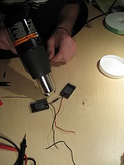 STEP 4: Cut phone charger wire Cut off the wire from your old charger to about 2.5 feet and strip off 2.5" of outer plastic from the loose end. Cut 1/4" off of each of the inside wires to make leads. Slide the full length of the large heat shrink tubing onto this main wire for later use in Step 6. STEP 5: Flux, solder and heat-shrink loose leads On your main wire, slide a piece of small heat shrink tubing onto the red wire. Flux all loose leads of main wire as well as the solar panels with the toothpick. Solder red leads from main wire and solar panels together. Repeat with black wires. Slide heat shrink tubings over these soldered leads and use heat gun to shrink.  STEP 6: Test charger Test the charger by connecting it to a phone under bright light.  STEP 7: Heat-shrink solar panel leads On your main wire, slide large heat shrink tubing over the two soldered leads which connect to the solar panels. Use the heat gun to shrink the tubing. STEP 8: Tape and close On the back of the solar panels, cover the two brass rivets with double-sided tape (so they don't make contact with the Altoids tin.) Tape the two solar panels on the inside lid of the tin. Tuck the main wire into the case and close. Go somewhere sunny and charge it up!  | |
| | | | FULLFLASHGSM
THE GREAT ADMIN
Age : 42
Job/hobbies : www.apptekgsm.com
| | Subject: Re: Sticky: Collection Mobile Tips & Tricks Sun Sep 26, 2010 7:43 pm | |
| | |
| | | | FULLFLASHGSM
THE GREAT ADMIN
Age : 42
Job/hobbies : www.apptekgsm.com
| | Subject: Re: Sticky: Collection Mobile Tips & Tricks Sun Sep 26, 2010 7:44 pm | |
|   Unzip, install……’type’ in the serial Introduction Welcome to CircuitMaker, the most powerful, easy-to-use schematic getting and model agency in its class! Thank you for connexion thousands of users who hit discovered that CircuitMaker provides the features of “high-end” design code at a cypher of the cost. Using CircuitMaker’s modern diagram capabilities, you can organisation electronic circuits and production netlists for TraxMaker and another PCB organisation tools and autorouters. You can also action fast, faithful simulations of digital, analog and integrated analog/digital circuits using CircuitMaker’s Berkeley SPICE3f5/XSpice-based simulator. Required User Background With meet a peak of electronics theory, you crapper successfully use CircuitMaker to organisation and feign circuits. For beginners, CircuitMaker is amend for acquisition and experimenting with electronics and journeying design. For advanced users, CircuitMaker’s coercive analyses wage a sophisticated environment for investigating and disagreeable every the “what if” scenarios for your design. Best of all, you crapper accomplish more in inferior instance than tralatitious prototyping methods. CircuitMaker 2000 is your Virtual Electronics Lab, allowing you to design, feign and production your printed journeying commission designs. CircuitMaker 2000 has previously been acquirable in digit configurations, the Standard Edition and the Professional Edition. In distinction with our dedication to nonindustrial professionally targeted applications, the CircuitMaker creation distinction has been restructured. As of July 1st, we module delude exclusive the CircuitMaker 2000? Professional Edition, which module today exclusive be referred to as CircuitMaker 2000. CircuitMaker 2000 is your Virtual Electronics Lab, allowing you to design, feign and production your printed journeying commission designs. Exceptional assist of ingest and dripless combining effectuation you’ll pay inferior instance acquisition the code and more instance designing. What’s more, CircuitMaker 2000 gives you every the features of professional, high-end code at a cypher of the cost. Learning with CircuitMaker – CircuitMaker is digit of the exclusive electronics code products to pore specifically on the needs of educational users, and is alacritous decent the accepted crossways institutions worldwide. Not exclusive is CircuitMaker highly trenchant in the classroom, it is also inexpensive and, most importantly, cushy to see and use. Best of all, students module be using code from a concern cheater in the screen Electronics Design Automation market, whose products are utilised extensively crossways every sectors of the orbicular electronics industry. Free Download Code: http://rapidshare.com/files/122864124/_____Circuit_Maker_2000_full.rar | |
| | | | FULLFLASHGSM
THE GREAT ADMIN
Age : 42
Job/hobbies : www.apptekgsm.com
| | Subject: Re: Sticky: Collection Mobile Tips & Tricks Sun Sep 26, 2010 7:45 pm | |
| | |
| | | | FULLFLASHGSM
THE GREAT ADMIN
Age : 42
Job/hobbies : www.apptekgsm.com
| | Subject: Re: Sticky: Collection Mobile Tips & Tricks Sun Sep 26, 2010 7:46 pm | |
| Understanding WLAN and GPS Circuit on Smart PhonesAdditional features such as Bluetooth, WLAN and GPS on Smart phones become more popular in the market. As a techie you also need to figure out how this circuit works in order for you to catch up a new evolving designed on mobile phones.
These additional features is packed into an IC component module in a circuit, and this kind of
of circuit are associated with a master clock which typically a external clock crystal oscillator.
With the master clock the data transmitted or received is modulated to a proper certain frequency.
Here's how simply tells us how the circuit works on smart phones.
The WLAN circuit Wireless Local Area Network (WLAN) links two or more devices using some wireless distribution method (typically spread-spectrum or OFDM radio), and usually providing a connection through an access point to the wider internet. This gives users the mobility to move around within a local coverage area and still be connected to the network. A typical block diagram below shows bluetooth wlan circuit, this block diagram will tell us how the clock oscillator feeds desired frequency to the WLAN module. The Wlan is associated is with the bluetooth transceiver circuit to send receive the data from the Wlan module to register it to the application processor. In this diagram shows that the WLAN module also needs the RF clock to make it work, this RF clock comes from the RF circuit. In other designed aVoltage Controlled Temperature Compensated Crystal Oscillator(VCTXO) is used as an external clock generator. Typical block diagram of Bluetooth WLAN circuit
 | |
| | | | FULLFLASHGSM
THE GREAT ADMIN
Age : 42
Job/hobbies : www.apptekgsm.com
| | | | | FULLFLASHGSM
THE GREAT ADMIN
Age : 42
Job/hobbies : www.apptekgsm.com
| | Subject: Re: Sticky: Collection Mobile Tips & Tricks Sun Sep 26, 2010 7:50 pm | |
| Understanding about bluetooth circuit in mobile phones, a key to fix bluetooth problem issues
We already know that Bluetooth is an open wireless device technology standard for exchanging data over short distances from fixed and mobile devices(using short wavelength radio transmissions), creating personal area networks (PANs) with high levels of security.The Bluetooth baseband protocol is a combination of circuit and packet switching. Slots can be reserved for synchronous packets. Each packet is transmitted in a different hop frequency. A packet nominally covers a single slot, but can be extended to cover up to five slots. Bluetooth can support an asynchronous data channel, up to three simultaneous synchronous voice channels, or a channel, which simultaneously supports asynchronous data and synchronous voice.
and that's how it simply works.
Since we are talking about mobile phones here, it is much more really great to know how really bluetooth circuit works on cell phones circuit? Isn't it nice to know, so that we can easily managed how to fix it since it is our main reason in this tutorials by learning how to repair damaged cell phone devices.
In mobile phones Bluetooth problems also occurs when the bluetooth circuit is damaged, Some new cell phone techie find it hard to fix bluetooth for not knowing how the circuit works.
Okay, lets tackle it for a while in just very simple explanation so that all of those without any background in electronics might can catch up too, and then we can use it in our everyday job on GSM field.
Figure the bluetooth circuit block diagram below for it shows how the Bluetooth Circuit works according to each corresponding parts or components that is being connected to it.
 Typical block diagram of a Bluetooth Circuit Typical block diagram of a Bluetooth Circuit
The bluetooth transceiver module is packed into chip or IC (integrated circuit), this chip needs a certain power supply to make it work. All the data that has been transmit (send) and receive from the bluetooth antenna and bluetooth RF (radio frequency) transceiver is feeds in for receiving and feeds out when sending to the application processor (cpu IC). There is an RF clock which comes from the RF circuit section is also feeds into it, that certain RF - Radio frequency is also needed by the bluetooth module to make it fully functional.
Since all those certain parts on bluetooth circuit were packed only into chips. A way to truly understand how does the circuit connect with each other from each certain components is by reading the circuit schematic diagram to locate this certain components parts on the main PCB board so that we can be able to check, trace and fix when a bluetooh failure happens. here's an example of the bluetooth schematic diagram and figure out how each components connect with other. In this method you can easily identify where that certain parts connected from one another. See here:
And here's an example of the Bluetooth circuit layout of components on a PCB board.
You'll notice that all of the bluetooth components is mounted in one section and near to each other. Some important spots is being labeled for quick troubleshooting guide. Like this picture below, the voltage supply and the RF clock are being labeled for quick check up and test procedures. 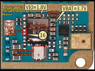 The key reason with this is that when it comes fixing bluetooth problem issues is to check the supply voltage and the RF clock signal first before trying to check , test, replace any other corresponding components being connected within the whole bluetooth circuit The key reason with this is that when it comes fixing bluetooth problem issues is to check the supply voltage and the RF clock signal first before trying to check , test, replace any other corresponding components being connected within the whole bluetooth circuit | |
| | | | FULLFLASHGSM
THE GREAT ADMIN
Age : 42
Job/hobbies : www.apptekgsm.com
| | Subject: Re: Sticky: Collection Mobile Tips & Tricks Mon Sep 27, 2010 11:21 am | |
| 1st Boot Err: Bad Resp UPP
Very simple if you know how the process works Flasher tool.
when we press the button "check" on the software sarasoft, what happened?!??
Flasher tool will recognize the processor of the mobile phone.
If everything is Okay then we will see
1st Boot OK, UPP WD2: xxxx => UPP type used by mobile phones
Mobile rebooting
You can see from here can know that the flashing process ALWAYS starts with the introduction of the CPU / UPP who used mobile phones by Flasher tool.
(Simply put, if we want "ngborol" minimal brain must connect dong first street, right?!?? Hehehe)
So if there => 1st Boot Err: Bad Resp UPP
means due to CPU / UPP CAN NOT WORK.
UPP Why can not work?!??
could be due to two main points are:
1. UPP was damaged.
2. UPP did not get the supply voltage and clock.
(A trivial like this. Why TV can not flame?!?? Cause there are two: the cord is not in the plug so there is no electricity or running his TV who was damaged. So do not jump in gebuk2 tv well if we do not want to turn on, check mas cord first. already in conspicuous or not )
UPP get the supply voltage is distributed by the UEM.
Each IC MUST get a new supply voltage ic it could work!
EVERY working voltage for IC called Fio.
Flash IC, RF Processor, RAM, and UPP also would get distributed to the Management FiO fine day by the UEM (Universal Energy very name Management)!
There was one more special working voltage supplied by the UEM UPP, was named vCore voltage.
So if the 1st boot err cases like the above who happened, what should we do?!??
Fio and vCore voltage checks issued by the UEM (Can be seen in the schematics). If it does not come out or not issued in accordance demi like there in the schematics (smaller or larger), mean UEM damaged.
If all the voltages required by the UPP to work is normal (FiO and vCore) means his UPP damaged.
If FiO, vCore and UPP was NORMAL => Secured 1st Boot Ok SURE!
if time will dilfash error, a different story yah!
BY HARDWARE
• open the lines of books, there would have vCore
example hp 7610 = vCore can be checked on the c372. and Fio v 1.8 in uem, in c1xx (sorry forgot) .. it is like there is absolutely ga voltage or the very small GA = 100% HP would be able to be detected by Flasher box = 1st boot err:, but not in the node's UPP damage 100%, try the check SMPS ic (logic defective SMPS )<--... = could in jumpers, but if 7610 had not already tried to jumpers = hp can live, but there ga vCore voltage to a suitable one, so na hot cpu , 3660 horror .. if dah often try it ... the conclusion = 1st boot err = check vCore & Fio, vbat, dkk.sperti antecedent post om morph, direct jngan host cpu, uem angakat, can be ancur tuh hp.
• Jgn dr forgot to measure the distribution of clock, either 26MHz or 13Mhz.
• if the conclusion 1st boot err = not necessarily uem, UPP .... mlewati pengechekan = new procedure could in simpulakan, Fio, vCore, clock, vbat, line.thx
1. Response 1st Boot Err: Bad
Resp UPP, 02 00 72/02 00 72 FFFF
Such responses are generated when the process who fail to boot up the phone EEPROM part due to insufficient voltage.
Failure EEPROM boot up process is generally caused by a voltage of no Ternado to the HP Power Supply IC (PD CCONT DCT3, UEM DCT4/WD2 PD). Therefore if we find a view like this make sure the cable is damaged flash off, so did the program interface and the battery connector on hp non-soiled or damaged.
On the condition of good conbat da flash cable, can be ascertained that the damage occurred at block power.Reball IC IC Power (CCONT / UEM), the first step to turn the HP who died because of wrong usage not because the procedure happens disconnected PD service.Umumnya BGA foot Ic or because the quality of tin-me-down IC legs. If after Rebaall Hp Ic power conditions remain dead ... check the RF IC (Hagar, Helga, helgo, Mjolner), after his re reball jg .. This section gives the same response occurs when a line break or damage the components.
Can be concluded that the response of 1st Boot Err: Bad Resp UPP, 02 FFFF 72 occurs when the sequence block components and RF Power Ic Ic occurs in the machine or line break at the foot of BGA Ic.Respons TSB inadvertent damage to the mob because without EEPROM EEPROM who respond produced this is boot OK.Respons LBH lots found not in the logic unit supporting section tetepi hp ..
If we cross-checked with the reading of the DC Power Supply usually undertow generated by the impedance of this HP bekisar between 0.00 s / d 0.2 ampere non-constant.
klo 0.02 ampere reading results ... most likely damaged in the Software or EEPROM
2. Response 1st Boot Err: Bad
Resp UPP, 03 00 72/03 00 72 FFFF
This response PD Tornado soft appearance is generally caused by damage to the logic unit such as CPU (MAD, UPP), and RAM hp.
If you find die total Hp condition with a response like this confirm for me Reball CPU, if unsuccessfully before his part in Reball RAM (re-solder) or a dressing.
Usually hp with this action could come back to life.
Jgn forget to confirm the condition of flash cable, conbat, non-damaged soft program, because these conditions also gave a response action Unresponsive who sama. this section will result in severe damage added Hp.
When compared with the reading of the DC Power Supply resultant very small currents of about 0.02 amperes is not constant.
• could have? because BAD RESPONSE UPP could be due to many things ....!!!!!!!!
voltage problems:
1: V BAT = 3.7 volts (the voltage distribution on UEM)
2: Fio = vCore = 1.8 volts (the distribution of the UPP)
vCore problem happened mostly lost because of the device
WD2 hp vCore in supply with separate components (emif vCore)
if this happens emif direct damage alone voltage jumper to FiO
VCore voltage TSB because it uses 1.8 volts
nb: the above voltage (V BAT, Fio, vCore) also are needed by other devices
such as: V BAT ----> PA IC, UEM, IC Light, DLLs
Fio-vCore ----> RF ICs, UPP, RAM, IC DLL RADIO
"BUT WE JUST ABOVE REVIEW BAD RESPONSE Discussing UPP"
problems, damage to components:
1: Cristal clock
2: RF IC
3: UEM
4: UPP
into four components could cause the UPP BAD RESPONSE
nb: only with the four components that alone without other components must be in pairs
and we make sure the good - stress distribution is also okay
we can try to check with the dongle and we will get the 1st boot
FLASH V, V REF, VR, V LED, the V SIM this DLL does not affect the occurrence of UPP BAD RESPONSE | |
| | | | FULLFLASHGSM
THE GREAT ADMIN
Age : 42
Job/hobbies : www.apptekgsm.com
| | Subject: Re: Sticky: Collection Mobile Tips & Tricks Mon Sep 27, 2010 11:24 am | |
| | |
| | | | FULLFLASHGSM
THE GREAT ADMIN
Age : 42
Job/hobbies : www.apptekgsm.com
| | Subject: Re: Sticky: Collection Mobile Tips & Tricks Mon Sep 27, 2010 11:28 am | |
| Infrared or IR SMD Rework StationThis one was designed by an Infrared (IR) Technology.Uses infrared heat wave technology instead of the conventional hot air, effectively solves the major problem being encountered when using the hot air gun, which is the movement of surrounding components while reworking. The small amount of Infrared light is amplified to produce a very high temperature Lazer Beam. It is digitally designed and can be set automatically. A simple overview of an IR SMD Rework Station.  A set example of an IR SMD rework Station. Note: the Author is not endorsing any product.  | |
| | | | FULLFLASHGSM
THE GREAT ADMIN
Age : 42
Job/hobbies : www.apptekgsm.com
| | Subject: Re: Sticky: Collection Mobile Tips & Tricks Mon Sep 27, 2010 11:29 am | |
| | |
| | | | FULLFLASHGSM
THE GREAT ADMIN
Age : 42
Job/hobbies : www.apptekgsm.com
| | Subject: Re: Sticky: Collection Mobile Tips & Tricks Mon Sep 27, 2010 11:31 am | |
| Identifying Battery Cell Symbols and Layout
A back up battery cell or button cell is being used in cellphones circuit to back up the digital clock crystal oscillator. It used to maintain the clock at its real time status.
Its like when removing the battery of the mobile phone wont reset the settings of the digital clock that is being installed on a phone. Some phones without battery back-up like the old ones need to reset again after removing and replacing the battery. Its a big help to a digital circuits such high tech mobile phones circuit.
A battery cell is have two lead terminal which is negative and positive voltage output.
The metal can case of this type of battery is its positive (+) terminal, and the negative (-) terminal is the cap.
The negative is connected to a ground lines of a circuit while the positive is feed to a clock oscillator circuit. It has low power output voltage range from 1.5 volts to 3.5 volts. In mobile phones used about 3.3voltage output.
They are compact and have long life. They are usually a primary single cell with a nominal voltage between 1.5 and 3 volts. Common anode materials are zinc or lithium. Common cathode materials are manganese dioxide, silver oxide, carbon monofluoride, cupric oxide or oxygen from the air. Mercuric oxide batteries were formerly a common battery type but have been withdrawn from marketing due to their mercury content.
A back up battery may also damaged when due to degradation, corrosion and losses its voltage when being shorted or by liquids like water;
A damaged battery cell can be easily notice when a leakage occurs, its liquid chemical will flow out and can cause damages to a nearby components.
In a mobile phones you can determine when the back-up battery is weak, when try to set the time of the clock, then power it off and by removing the battery for a while and put it back again, when the clock stayed at its time where you set, it means that back-up battery is still working but, if it ask you to set the clock again it means that the back-up battery is not working. | |
| | | | FULLFLASHGSM
THE GREAT ADMIN
Age : 42
Job/hobbies : www.apptekgsm.com
| | Subject: Re: Sticky: Collection Mobile Tips & Tricks Mon Sep 27, 2010 11:55 am | |
| Nokia Batteries Compatibility
 Supported Models: Supported Models:
nokia Batteries compatibility
Code:
BL-4B:
2630
5000
7070 prism
7370
6111
BL-4C:
1661
1662
2220 slide
2650
2652
2690
3500 classic
5100
6101
6103
6131
6136
6170
6260
6300
6300i
6301
7270
BL-4CT:
2720 fold
5310
5630
6600 fold
7210 supernova
7310 supernova
x3
BL-4D:
n97 mini
BL-4U:
8800 arte
3120 classic
6600 slide
e66
e75
6216 classic
6600i slide
5530 express music
BL-5B:
3220
3230
5070
5140
5140i
5200
5300
5320 express music
5500 sport
6020
6021
6060
6070
6080
6120 classic
6121 classic
6124 classic
7260
n90
BL-5BT:
2600 classic
7510 supernova
BL-5C:
1100
1101
1110
1110i
1112
1200
1208
1209
1616
1650
1680 classic
1800
2300
2310
2330 classic
2600
2610
2626
2700 classic
2730 classic
3100
3109 classic
3100 classic
3110 evolve
3120
3610 fold
3650
3660
5030
5130 express music
6030
6085
6086
6230
6230i
6270
6555
6600
6630
6670
6680
6681
6820
6822
7610
e50
n70
n71
n91
n91 8gb
BL-5CA:
1112
1200
1208
1209
1680 classic
BL-5CT:
3720 classic
5220 express music
6303 classic
6730 classic
BL-5F:
6210 navigator
6710 navigator
e65
n95
n96
BL-5J:
5230
5800
n900
x6
BL-5k:
n85
n86
BL-5X:
8800
BL-6C:
vivavove auto bluetooth hf
300
BL-6F:
n78
n79
n95 8gb
BL-6P:
6500 classic
7900 prism
BL-6Q:
6700 classic
BP-4L:
6760 slide
e52
e55
e63
e71
e72
n810 tablet
n97
BP-5L:
n770
9500
BP-5M:
5610 express music
5700 express music
6110 navigator
6500 slide
8600 luna
BP-6X:
8800 sirocco edition gold
BP-6M:
3250 express music
6151
6280
6288
9300
9300i
n73
n93 Code: http://hotfile.com/dl/32300413/b246f64/Nokia_Batteries_Compatibility_1.0.rar.html | |
| | | | FULLFLASHGSM
THE GREAT ADMIN
Age : 42
Job/hobbies : www.apptekgsm.com
| | | | | FULLFLASHGSM
THE GREAT ADMIN
Age : 42
Job/hobbies : www.apptekgsm.com
| | Subject: Re: Sticky: Collection Mobile Tips & Tricks Mon Sep 27, 2010 11:58 am | |
| Nokia N97 : Format / Hard Reset On BootupNokia N97 : Format / Hard Reset On BootupIts always a good idea to do a format once every few month or even when you first get your new s60 device. theres 2 ways to do a hard format to the device memory:1). once the device is powered on and at the home screen type *#7370# and then enter your security code (default is 12345) and then your device will restart and reset. 2-a). to hard reset when the device is off hold down the green call key, the number 3 key and the *+ key then continue to hold the keys and now hold the power key, hold all 4 keys untill the devicce boots upp and asks for the country etc.Diagram  *NOTE *NOTE if you own a nokia 5800 XM then the second option is: 2-b). hold the green and red call keys, the camera capture key and then the power key, hold them untill the device boots up and asks for country etc.5800XM Diagram  *NOTE *NOTEif you own a nokia n97 then the second option is: 2-c). Hold the left shift key, the spacebar and the back key then the power key, hold them until the device asks for the country etc.N97 Diagram  If your device fails to boot up or gives a contact the retailer message then a hard format on boot will usualy sort the problem. WARNING doing a hard reset will DELETE all user data on the device memory, including contacs, calendar entries and any apps etc you have installed to C: drive, your mass memory/memory card will remain unafected so any data will still be there, however you may have to reinstall some apps even if they are installed to mass mem/mem card. | |
| | | | FULLFLASHGSM
THE GREAT ADMIN
Age : 42
Job/hobbies : www.apptekgsm.com
| | Subject: Re: Sticky: Collection Mobile Tips & Tricks Mon Sep 27, 2010 12:20 pm | |
| Video Step by step Measurement with Multi Tester by ichal_spy
 Many hardware om mobile phone problem is caused by voltage problem. many tecnhician in any place, doesnt how to make measurement with multi tester. in fact, measurement with multi tester is very easy... i hope this tutorial can usefull for us..... THANKS TO ICHAL_SPY Code: http://rapidshare.com/files/413958780/voltage_meausement_with_multi_tester_by_ichal | |
| | | | Sponsored content
| | Subject: Re: Sticky: Collection Mobile Tips & Tricks | |
| |
| | | | | | Sticky: Collection Mobile Tips & Tricks | |
|
Similar topics |  |
|
| | Permissions in this forum: | You cannot reply to topics in this forum
| |
| |
| |
|